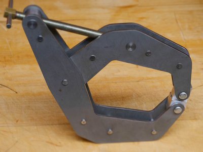
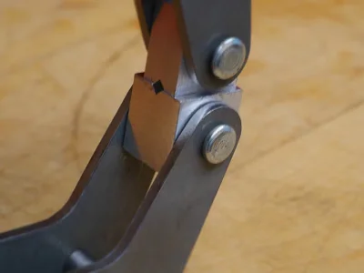
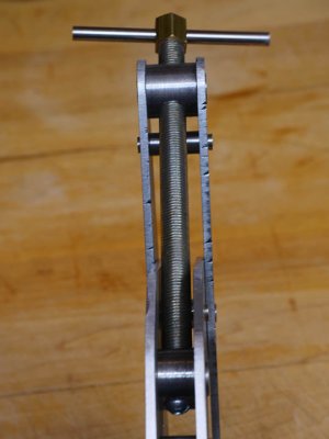
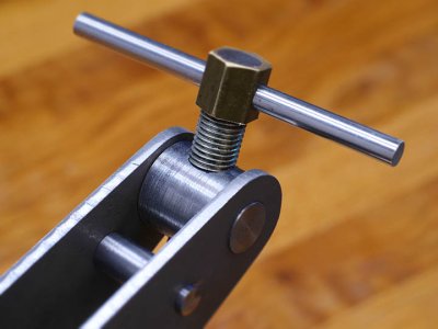
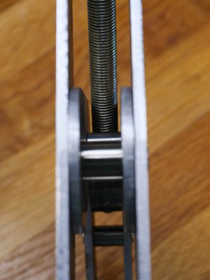
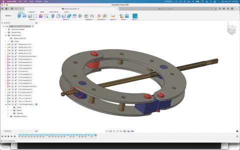
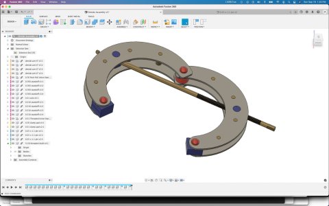
This summer I have been designing and building my own version of Kant-Twist clamps in 3 sizes - 2.5", 4.5" and 6". I have the 6" one finished and will include pictures. I am happy with the design and have learned a lot from the process of building my first clamp. I had a decent quantity of the various arms manufactured locally, using a laser cutter, and this has worked well. Of special note is that the design includes all necessary holes - very precisely located to make the clamp go together accurately and work smoothly. I created a document with many more details and will attach that for anyone who wants to read the fuller story. This documents covers the flaws in the clamps I purchased, the major design goals of my re-design, the process of making the first clamp and some prices.
Happy to make available sets of the arms to anyone interested - details in the document attached. My thinking is that only a few of you would want to read 5 pages of details on this subject! But, for anyone interested, the complete story - so far - is in the attached PDF file.
Happy to make available sets of the arms to anyone interested - details in the document attached. My thinking is that only a few of you would want to read 5 pages of details on this subject! But, for anyone interested, the complete story - so far - is in the attached PDF file.