• Spring 2024 meetup in Calgary - date Saturday, April 20/2024. discussion Please RSVP Here to confirm and get your invitation and the location details. RSVP NOW so organizers can plan to get sufficient food etc. It's Tomorrow Saturday! you can still RSVP until I stop checking my phone tomorrow More info and agenda
  • We are having email/registration problems again. Diagnosis is underway. New users sorry if you are having trouble getting registered. We are exploring different options to get registered. Contact the forum via another member or on facebook if you're stuck. Update -> we think it is fixed. Let us know if not.
  • Spring meet up in Ontario, April 6/2024. NEW LOCATION See Post #31 Discussion AND THE NEW LOCATION

New Never-Twist clamps

kevin.decelles

Jack of all trades -- Master of none
Premium Member
[mention]Janger [/mention] have you figured out a price yet? [emoji3]


Sent from my iPhone using Tapatalk
 

Janger

(John)
Administrator
Vendor
Another thing you might consider is the clamp faces being flat like most clamps I think it would be useful to have a v cut in opposite the main gripping flat that way they could be rotated to hold round to flat or round to round without skating they could have a spring and ball locating the position keeping them in place. I would cut the v on both but at 90* to each other for 2 directions of holding.

Got it!
 

Attachments

  • dimide 3.jpg
    dimide 3.jpg
    249.8 KB · Views: 6

Janger

(John)
Administrator
Vendor
Upgraded from peened rivets to screws. Screw models are from McMaster Carr.
 

Attachments

  • 1632108972843.png
    1632108972843.png
    877.1 KB · Views: 14
Last edited:

eotrfish

Super User
Janger

To confirm...

The handle end of the threaded rod is retained in the square block with a C-clip.

Starrett 164C 06_LI.jpg

The knurled handle presses on the square block and the rod simply spins inside the block. You got it right. The threaded rod and handle is all one piece.

Starrett 164C 05_LI.jpg

The far end of the threaded section has a stop washer which is retained by a C-clip.
Starrett 164C 04_LI.jpg

I think your decision to opt for screws rather than peened rivets is a good one. You can change the anvils to V / Flat / Radiused or whatever your heart desires in less than a minute.
 

PeterT

Ultra Member
Premium Member
The only other thing I'd suggest is how to size a graduated set, like small / medium / large for example. Looks like the width is about 2X the distance between pads & jack screw. So big clamps may not be appropriate for small jobs given the overhang. And when they are wide open you lose a bit of mechanical advantage. Some things may scale, other things (like fasteners, therefore threaded holes, jack screw... maybe even plate thickness) may be different for different sizes. I'm a 1-IKEA wrench kinda guy, but sometimes that's just not possible.

1632163064234.png
 

Tom O

Ultra Member
I was just thinking all these clamps just work clamping I think I’d redesign the frame so the jaws still rotate but has clearance on the outer edge so it could be used to spread / align your builds as most people don’t have a helper. Maybe just a drop in jaw.
 

Tom O

Ultra Member
The only other thing I'd suggest is how to size a graduated set, like small / medium / large for example. Looks like the width is about 2X the distance between pads & jack screw. So big clamps may not be appropriate for small jobs given the overhang. And when they are wide open you lose a bit of mechanical advantage. Some things may scale, other things (like fasteners, therefore threaded holes, jack screw... maybe even plate thickness) may be different for different sizes. I'm a 1-IKEA wrench kinda guy, but sometimes that's just not possible.

View attachment 17173
And that is probably why they were discontinued you could probably move the rod to the left of it like the can’t twist because the more you get to the pivot the less clamping force.
you could extend the arm to use the same system as the can’t twist.
 

Brian26

Active Member
Premium Member
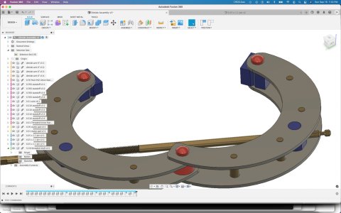
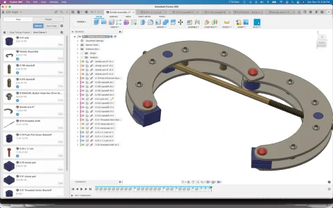
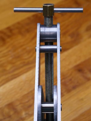
I got busy and designed up a version of the dimide in Fusion 360. This is about a 6" throat depth version.

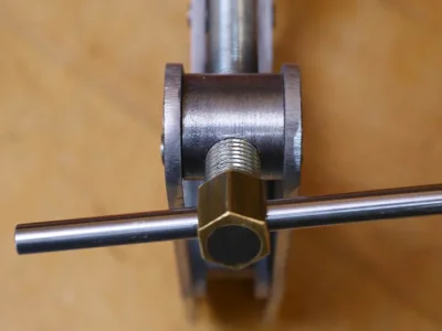
I've been mulling over options on how the threaded rod would exert the clamping pressure. The area in red circle is still to be defined. I was thinking of using two locking collars on the threaded shaft - one on each side of the stand off - probably with flats or even holes going right through the threaded rod for a pin. Any suggestions on this? I see on the starett 164 there are two square blocks on the shaft. The one located on the threaded section is clearly threaded and moves back and forth exerting the clamp pressure. The closer one at the handle end though is not so clear what it is doing. It seems it must be fixed in place yet also allow the shaft to spin - @eotrfish how does that part work? Perhaps the knurled handle part presses on the square block and the rod simply spins inside the block? Is the threaded rod and handle all one piece? and thanks for posting that disassembled picture it's interesting.

Does the far end of the threaded section have a screw on stop?

I also like the standoffs are internally threaded and use machine screws for assembly. And the bend in the arms means you only need one length of standoffs and only one clamp pad depth - very clever Starett. (Edit -> well not quite looks like there are a few different lengths of standoffs) And I see the standoffs holding the clamp pads have a different head diameter - I wonder why they did that?

John
Wonderful drawings. Very clear and helps me understand that this type of clamp does have a deeper throat when fully open - a big plus, providing you do not have to close it too much. Your red circle concern could be solved the way Dimede did - by using right and left hand threads. If that is not practical for some reason, then this is bound to be an area for concern, because of the tremendous forces involved. You could probably find a solution for up to one ton of force - but this design goes way beyond that, and so a hefty part will be needed here.
Regarding the threaded standoffs - it is a great idea, and the guy in Winnipeg uses that for his design. It is more fussy however and would take lots longer than peening the ends. Regarding peening, I wonder if your fantastic Fusion 360 designs could easily be modified to show a longer end on the 8 standoff pins? Or, alternately, leave them as is and add a threaded hole? Both designs would work well, and any maker would be happy with either choice.
Great work - and I like the way you think!
P.S. - I plan to take some more detailed pictures of the clamp I made and post them. Maybe later today?
 

Brian26

Active Member
Premium Member
[mention]Janger [/mention] have you figured out a price yet? [emoji3]


Sent from my iPhone using Tapatalk
Kevin
I did not want to be too forward on this forum, so I put the prices in my PDF attachment. Let me know if I should send you that file separately, and I will gladly do it. Would need an e-mail address - it is way too large for a phone to handle I think. Cheers, Brian
 

Janger

(John)
Administrator
Vendor
John

Regarding the threaded standoffs - it is a great idea, and the guy in Winnipeg uses that for his design. It is more fussy however and would take lots longer than peening the ends. Regarding peening, I wonder if your fantastic Fusion 360 designs could easily be modified to show a longer end on the 8 standoff pins? Or, alternately, leave

Brian
How far above the surface should the standoffs stick out for peening?
J
 

Brian26

Active Member
Premium Member
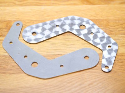
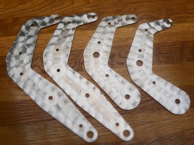
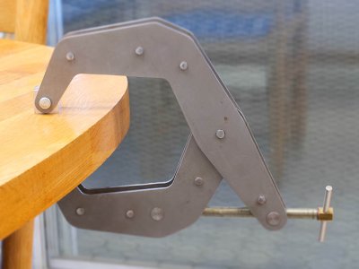
This summer I have been designing and building my own version of Kant-Twist clamps in 3 sizes - 2.5", 4.5" and 6". I have the 6" one finished and will include pictures. I am happy with the design and have learned a lot from the process of building my first clamp. I had a decent quantity of the various arms manufactured locally, using a laser cutter, and this has worked well. Of special note is that the design includes all necessary holes - very precisely located to make the clamp go together accurately and work smoothly. I created a document with many more details and will attach that for anyone who wants to read the fuller story. This documents covers the flaws in the clamps I purchased, the major design goals of my re-design, the process of making the first clamp and some prices.

Happy to make available sets of the arms to anyone interested - details in the document attached. My thinking is that only a few of you would want to read 5 pages of details on this subject! But, for anyone interested, the complete story - so far - is in the attached PDF file.

More Pictures!
 

Attachments

  • Fancy Arm.jpg
    Fancy Arm.jpg
    81.8 KB · Views: 10
  • P1034522.JPG
    P1034522.JPG
    54.1 KB · Views: 9
  • P1034548.JPG
    P1034548.JPG
    84.9 KB · Views: 10
  • P1034526.JPG
    P1034526.JPG
    60.4 KB · Views: 10
  • P1034518.JPG
    P1034518.JPG
    49.1 KB · Views: 9

Janger

(John)
Administrator
Vendor
Brian - how did you do the fancy ones finish?

Everybody - if I made the standoffs from aluminum would there be any strength concerns? It would be easier to thread…
 

Brian26

Active Member
Premium Member
Brian - how did you do the fancy ones finish?

Everybody - if I made the standoffs from aluminum would there be any strength concerns? It would be easier to thread…
John
To make the arms look like the picture, I used a 1" abrasive pad I got from Amazon in my milling machine - but any drill press will do this. These pads screw into an adaptor which you also need. I bought a package of 30 pads at once, and the first pad did all four arms, and still has life left. I free-handed the whole process, moving the arm perhaps 5/8" each time. Each "scratch" took only a few seconds.

Regarding the aluminum standoffs, I had not thought about aluminum - but it should work well. I think it would lower the strength a bit, but the savings in time might be worth it. One thing I do know from being almost finished making the second clamp (with the fancy-looking arms) is that it is a challenge to drill and tap a hole into steel for a 10-24 bolt. If I recall correctly, you intend to make a clamp using threaded ends on each standoff - an elegant solution I believe.
 

Brian26

Active Member
Premium Member
aluminum would be fine. the standoffs don't get that much stress...
I think that aluminum would work very well if, like John you intend to drill and tap the standoff ends for small bolts to hold things together, and not use peening like I did. I think aluminum might be too soft for peening and so I did not even think of that. I now am thinking that brass might be better than aluminum? Very easy to machine, drill and thread. For the record, I have made the central pivot for my second and fancy clamp from brass. There will be pressure on this pivot point, but the diameters are large enough so it should not be a problem. We shall see...
 

Brian26

Active Member
Premium Member
Busy yesterday and today making the "internals" for the second clamp. Ready now for the installation. I made the handle so that it slides this time around. Also used 7/16-14 threaded rod instead of 7/16-20 so the clamp will open and close faster. Have a look: P1034568.JPG P1034570.JPG P1034571.JPG P1034572.JPG P1034574.JPG P1034576.JPG
 

Tom O

Ultra Member
Looks good but I think it would be more comfortable tightening it with round caps instead of square ones.
 
Top