• Scam Alert. Members are reminded to NOT send money to buy anything. Don't buy things remote and have it shipped - go get it yourself, pay in person, and take your equipment with you. Scammers have burned people on this forum. Urgency, secrecy, excuses, selling for friend, newish members, FUD, are RED FLAGS. A video conference call is not adequate assurance. Face to face interactions are required. Please report suspicions to the forum admins. Stay Safe - anyone can get scammed.

New lathe choices in Canada

I don't recall how much counterweight I have in there. It has been years since I built it. Now that I type, I think my counterweight was some old leaf springs, whatever would fit in the 4" tubing. No where near what the plans called for but I thought I would try it and have not looked at it since. Seems to work. It does lift very well for its size. If the object was not so valuable, I would have been a little more carefree with it but I wanted to just lift it off of the pallets and bring it to the end of the trailer. If need be, I would have put it on the ground or even onto the bench but that would mean working in the exhaust in the garage and a bit of juggling. I was by myself at the time so did not go too high. Dan was not available till later.

For those interested, the plans are the CADplans 821
 
Congrats on getting the lathe into your shop and safely onto the pedestal.

The key does not work on 1 of the three.

That is not normal, but I guess if the cam lock square is at it’s smaller limit for size and the key is at it’s upper limit, there is the chance that they won’t engage. Measure them. Check for and deburr both of them. If still no go, I would take a bit off the key.

Most folks make their own, longer, key as the factory ones are “knuckle busters” by usually being too short to clear the headstock casting.

Would be a good first project for the new machine...
 
Congrats on getting the lathe into your shop and safely onto the pedestal.


That is not normal, but I guess if the cam lock square is at it’s smaller limit for size and the key is at it’s upper limit, there is the chance that they won’t engage. Measure them. Check for and deburr both of them. If still no go, I would take a bit off the key.

Most folks make their own, longer, key as the factory ones are “knuckle busters” by usually being too short to clear the headstock casting.

Would be a good first project for the new machine...

Thanks @RobinHood ...It is not that the tool will not fit into the socket, but rather, the handle conflicts with the headstock. Just that angle that is a little bit off! I will play around with it but good idea on making a new longer one. Even the sockets that are oriented in a way that works still look like bandaid territory
 
I spent the morning cleaning the machine, deburring where I can, fitting the rear chip guard, etc. , and just learning a bit about the machine. I had some time to figure out some of these new controls. I found it very hard to get the carriage change gear box into any or all gears. I was trying with the machine off. I also found that with the power feed engaged in the left to right position (reversed?) there was a very loud "gears slight not meshing " noise coming from the machine but in neutral or normal (right to left), it was quiet. I took a video and emailed the link to Precision Matthews. The reply I got was that this is normal. It sure does not sound normal so I kept exploring. I found that the lever has 2 stops to the right. The first one would tend to get missed and right into the second one, which seems to move the gear past a good mesh and into a slight miss. I emailed PM back and the tech says he has the same machine and has just put up with the noise. I am hoping he gets back to me with a similar finding and can advise future customers with the advice to not "over engage" the feed lever to the right. Moving it to the left, I think the throw lever in the gear box hits the side and prevents it from going too far.

And then, I actually, made some chips and played with power cross feed and feeds, speeds, etc. Wow! Big step up from what I am used to....:)

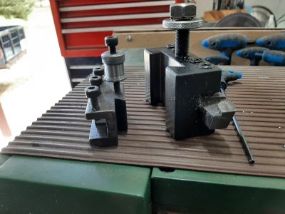
It came with 5 tool holders for the BXA holder. I cleaned those up and checked them out. Massive compared to the QCTP on my little B2227. Interesting, found a knurling tool (did not recall it came with one) and on the backside, it holds a regular tool. I will need a much larger boring bar I guess....everything just got bigger. :eek: And probably need more regular tool holders too..... Might have to come out of retirement....:rolleyes:

Cheers,


@ShawnR : sounds exactly like poor meshing gears. Could be just a proper detent adjustment. Our lathe at work has three settings for speed and a loose set screw and slight gear adjustment made a big difference
 
What a joker reply from PM
No ty for 7500$
There are ball detents with springs and set screws compressing the detent balls. Crank in on the screws.... so when you hit the designed spot for the balls to fall into ( a hole on the casting ) it will engage with force and you will know youre home. As apposed to over shooting and thus your mis match gears.

Gluck
 
Agree that the ball detente may be influencing the position engagement where it's not quite 'in'. Check your manual but typically there is a roll pin through the knob & shaft to remove. Then carefully remove the knob because the spring & ball may want to fly across the room. It could be the detente is drilled proper but filled with debris. Or its a bad hole & the ball doesn't fit proper. (Careful here you dont want to modify unless you are sure). If that all checks out you may have to inspect the lever /slider mechanism inside that is displacing the gears which is what the shafts are moving.

Also when you shift a lever into gear its common to have to rotate the chuck just a bit just to get the gears to engage into phase with one another. Just pushing the lever is forcing them to try & align but that doesn't work well if they happen to be further out of phase. I don't think there is anything like a synchro mechanism on these machines
 
Shawn, is the change gear quadrant adjustable? My Emco , which may be similar, will make a lot more noise if the gears are too tight. Post a pic
 
When i took a SAIT night gunsmithing course one of the first things we were shown to lookout for was improper gear meshing on the outboard gearing that runs the power feed directional shaft & feed speed gearbox. A lathe was set up purposely to run noisily and then re-set to run smoothly....I was surprised by how noisy a gear train could be with a little bit of incorrect gear meshing.
While I have never had ant problem with power feed gearing , I did have a bunch of adjustments that had to be done in the headstock gearbox so gears mesh lined up with the lever detents (mine has levers, the one in the video here has those two 'arrowed" knobs). In my lathe, and i suspect yours will be the same as they originate from the same side of the ocean I think, I soon run into problems shifting gears and having the detents not place/lock the change-gears in the proper place. So, off came the gearbox cover and I discovered the problem immediately. The locking grub screws that lock the shift forks to the shaft from the outside levers couldn't be tightened enough to hold with much resistance it the gears didn't instantly line up . Two reasons I couldnt tighten them up enough ....first was constant oil splash kept the shafts very well lubed up and the second, mostly the culprit was the shift fork casting was not very beafy and I was very leery of stripping the threads on a "not very readily replaceable part". When i first removed the cover I could see that some of the gears, when i thought they were in position were actually only engaging corner-to-corner, just enough to drive the headstock.

The fix was really quite easy, and I suggest you have a look under the cover on your new lathe. I positioned the sliding change gear for each shift fork on a gear that it was supposed to run on, with the grub screw removed I center punched the shaft thru the screw hole. Now I manufacture a center-drilled drill guide that would slip fit into the screw hole to protect the threads from damage and drilled a small dimple into the shaft for the grub screw to embed into. That was 15 years ago and they have yet to come loose since then.
 
Yuchol from Woods Creek Workshop had to adjust the detents on his Jet lathe, He did a YT video on it a while ago
 
suggest you have a look under the cover on your new lathe
That would also give you a chance to see how clean it is inside. There are horror stories out there about how much casting flash /sand and swarf is left in the bottom of a head stock from the factory.
 
Congrats on the new machine.

I wonder if the tech is the owners son.

I'm in the same boat going from the SM9 to the SM1120, bigger tool post, bigger boring bars, bigger centers and the list goes on, but totally worth it.

lol..don't know if he is related. I think he was young and inexperienced. Just happened to answer the email. I cc'd sales on the correspondence to let them in on conversation.

Yes, as to bigger is better. The rigidity is noticeably better, resulting in a better finish, so far. Attached photo shows difference in size of tool holders.
 

Attachments

  • QCTP .jpg
    QCTP .jpg
    268.2 KB · Views: 12
Shawn, is the change gear quadrant adjustable? My Emco , which may be similar, will make a lot more noise if the gears are too tight. Post a pic

Honestly, I am not overly worried about it. Now that I know what is going on, it is easy to deal with....but, due to the response here, maybe I should be more concerned. :confused:

I will take another look at it. I don't want to void my warranty messing with something that is like a manual transmission,,,you can find the wrong gear if looking for it. Having said that, it would be nice to just throw the lever into position. I am giving my self time to get used to it...maybe it is my small but generally ham fisted actions causing the issue...;)

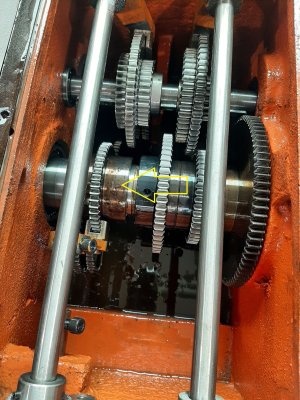
Here is the photo. As shown, the arrow points to the feed gear. In the photo, it is in the correct position for a right direction feed, and this position does have a corresponding "endent?" where it should be. However, when moving it, cause things are still tight, I suspect, it is easy to overshoot this position and move the gear more to the right, causing the noise in the video. The same distance is not attainable when going in the other direction cause the gear is limited by the wall of the gearbox.

I will compare what is there to what the parts diagram shows.
 

Attachments

  • Headstock gears edited.jpg
    Headstock gears edited.jpg
    446.6 KB · Views: 26
Yuchol from Woods Creek Workshop had to adjust the detents on his Jet lathe, He did a YT video on it a while ago

Interesting...I will go take a look. Thanks!

That would also give you a chance to see how clean it is inside. There are horror stories out there about how much casting flash /sand and swarf is left in the bottom of a head stock from the factory.

I will do that. Good idea. I only looked at the gears the one time I was in but will do a better look this time.
 
When i took a SAIT night gunsmithing course one of the first things we were shown to lookout for was improper gear meshing on the outboard gearing that runs the power feed directional shaft & feed speed gearbox. A lathe was set up purposely to run noisily and then re-set to run smoothly....I was surprised by how noisy a gear train could be with a little bit of incorrect gear meshing.
While I have never had ant problem with power feed gearing , I did have a bunch of adjustments that had to be done in the headstock gearbox so gears mesh lined up with the lever detents (mine has levers, the one in the video here has those two 'arrowed" knobs). In my lathe, and i suspect yours will be the same as they originate from the same side of the ocean I think, I soon run into problems shifting gears and having the detents not place/lock the change-gears in the proper place. So, off came the gearbox cover and I discovered the problem immediately. The locking grub screws that lock the shift forks to the shaft from the outside levers couldn't be tightened enough to hold with much resistance it the gears didn't instantly line up . Two reasons I couldnt tighten them up enough ....first was constant oil splash kept the shafts very well lubed up and the second, mostly the culprit was the shift fork casting was not very beafy and I was very leery of stripping the threads on a "not very readily replaceable part". When i first removed the cover I could see that some of the gears, when i thought they were in position were actually only engaging corner-to-corner, just enough to drive the headstock.

The fix was really quite easy, and I suggest you have a look under the cover on your new lathe. I positioned the sliding change gear for each shift fork on a gear that it was supposed to run on, with the grub screw removed I center punched the shaft thru the screw hole. Now I manufacture a center-drilled drill guide that would slip fit into the screw hole to protect the threads from damage and drilled a small dimple into the shaft for the grub screw to embed into. That was 15 years ago and they have yet to come loose since then.

Very interesting. I certainly hope I don't have to go that far but it will be good to explore this. Thank you!!
 
That sounds exactly like my SB did when I engage the back gears. Turned out the gear mesh was waaaay loose. Fortunately I could adjust that which solved the problem.
I did notice that it only occurs when feeding away from the chuck. Or am I mistaken?
 
Shawn

Another thing you could do is search a thread on the hobby-machinist forum and see what is there for answers, or start a thread, Matt does occasionally pop up on there and has helped solve issues that pop up with his machines
https://www.hobby-machinist.com/forums/precision-matthews-quality-machine-tools.172/

Wayne

Matt actually responded to one of my emails when I was trying to get the credit issued (remember the price went up between my quote and the actual purchase...? they honoured the quote but it took a few emails and Matt finalized it) And, as you point to, Precision Matthews has a whole forum dedicated to their machines. I posted there regarding spacing on the cast iron bases and got some good responses. One guy there was receiving the same lathe from the same shipment.

I kind of think this (clashing issue) is user error or new equipment familiarization stuff. It would be nice if the user could just throw the gear in but I don't expect that. After reading the comments here, I went back out to experiment a bit more. I found that there is an indent in the right position, but it is very subtle. And then it is possible to go beyond it into the gear rubbing zone..which I was doing.. So, as a new user, I was going past it. LIke my wife,.... I blame me........o_O..........................;). As I get to know the machine, I will learn to detect the indent. I had no problem today switching it into the correct position. Interesting, the lathe shut off if I started it while the feed screw was in the "noisy" position but was ok to start with the power feed in the proper position...sooo, some switch is properly set somewhere, I think.

I would like to tweak it so I cannot overshoot, but honestly, now that I know what I am doing, it won't be an issue.

Cheers,

Shawn
 
Back
Top