• Spring 2024 meetup in Calgary - date Saturday, April 20/2024. discussion Please RSVP Here to confirm and get your invitation and the location details. RSVP NOW so organizers can plan to get sufficient food etc. One week to go! More info and agenda
  • We are having email/registration problems again. Diagnosis is underway. New users sorry if you are having trouble getting registered. We are exploring different options to get registered. Contact the forum via another member or on facebook if you're stuck. Update -> we think it is fixed. Let us know if not.
  • Spring meet up in Ontario, April 6/2024. NEW LOCATION See Post #31 Discussion AND THE NEW LOCATION

Need Some 8" Round Stock Cut - Calgary

YYCHM

(Craig)
Premium Member
Hi Craig, following your thread with lots of interest nice work however, somewhere along the way I missed out on what your project is.

From your latest photos I assume you're making a taper turning attachment for you lathe so you can reproduce tapers?

Thanks for hitting the like button, appreciate that.

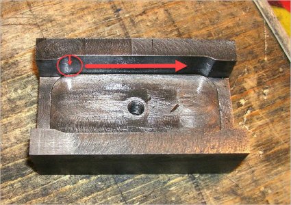
Ya, this thread kind of morphed into a project thread. You are correct, it's an improved (better tolerance) shoe for the taper attachment on my lathe. I never received the original with the lathe when I bought it.
 

Dusty

(Bill)
Premium Member
Hi Craig, what name brand of mill/drill do you have? How on earth do you keep your round column mill square with the table? Or is it something like playing horse shoes when close counts. Must be a simple method of squaring the head to the table every time the heads moved.
 

DavidR8

Scrap maker
Administrator
Moderator
Premium Member
Hi Craig, what name brand of mill/drill do you have? How on earth do you keep your round column mill square with the table? Or is it something like playing horse shoes when close counts. Must be a simple method of squaring the head to the table every time the heads moved.
Hi Dusty, do you mean keeping the head in tram or returning to position if the head shift or is intentionally moved?
 

YYCHM

(Craig)
Premium Member
Hi Craig, what name brand of mill/drill do you have? How on earth do you keep your round column mill square with the table? Or is it something like playing horse shoes when close counts. Must be a simple method of squaring the head to the table every time the heads moved.

It's a House Of Tools branded RF30 clone. About all that you can do is eye ball the head to table alignment. If you plan your work out such that you don't need to adjust the head once you're setup it's not a big deal.
 

Dusty

(Bill)
Premium Member
Hi Dusty, do you mean keeping the head in tram or returning to position if the head shift or is intentionally moved?

Hi David, hesitated to use the word tram only because I view that when one angles the head port or starboard. Aircraft talk, port has 4 letters and so does left easy to remember. LOL

Yes returning the head to the same square position after you loosen the locking nuts then crank the head up or down.
 

DavidR8

Scrap maker
Administrator
Moderator
Premium Member
Hi David, hesitated to use the word tram only because I view that when one angles the head port or starboard. Aircraft talk, port has 4 letters and so does left easy to remember. LOL

Yes returning the head to the same square position after you loosen the locking nuts then crank the head up or down.
On my RF clone, I've found that the head is very repeatable for squareness/tram. I managed to tram the within .0001 on all four quadrants so I'm pretty happy with that.
 

Hruul

Lee - metalworking novice
There are modifications that you can buy or make that are supposed to keep the head square to the table when you raise and lower in the middle of an operation. Do not know anyone personally that has one that can confirm the accuracy that the mod provides. ThatLazyMachinist on Youtube covers order of operations on a round column mill to keep from having to adjust the head height once an operation is begun.
 

johnnielsen

John (Makonjohn)
Premium Member
If you want the head of this type of Mill to remain aligned, the rack can be fastened to the column with countersink head Grade 8 bolts. Alignment will be maintained as long as you don't yank on the head.
 

johnnielsen

John (Makonjohn)
Premium Member
You pull the head off and dismount the column followed by laying the column down on the table. Then you can scribe a line on the column and align the rack to it. Predrill and countersink the rack prior to alignment. Spot drill the column through the rack. Drill and tap the holes in the column. Mount the rack on the column and reinstall it. Drop the head onto the column. To account for wear, push the head sideways gently so it feels solid and clamp the head. Always push it gently in the same direction when locking the head. If the sides of the rack are worn unevenly, you will have to refurbish it.
Being aware of the wear in your machine and using technique to overcome it is part of the game.
 

Dusty

(Bill)
Premium Member
Thanks John for your details would think this a positive way to keep the mill head trued to the table.
 

YYCHM

(Craig)
Premium Member
Finished my TA shoe today.... But not without a major ooops.

CISHOE9.JPG


As I was attempting to mill that sidewall recess the whole work piece pulled out of the vise. Made quite a mess of things. You can still see a remnant of the damage on the bottom face. It actually stalled the 2HP mill and I'm kind of surprised it stalled and didn't break the end mill. I may have damaged my ER20 collet and holder though:mad:. I was so PO'd I didn't bother taking a pic of the carnage. I did manage to salvage what I was left with and achieved the shoe to slide bar tolerance I was hoping for, so I guess you could call it a success.
 
Last edited:

Dusty

(Bill)
Premium Member
Well done Craig, like a man who sticks with a project right to the end regardless of unexpected mishaps out of the blue.
 

PeterT

Ultra Member
Premium Member
...the whole work piece pulled out of the vise

Do you recall the conditions leading up to the event? For example:
- climb milling direction or conventional direction?
- was the bottom of the end mill in contact with the floor the same time it was cutting on the EM side?
- did you feed downward in the vertical direction by some amount, or feed inward into the part?
- what kind of depth of cut?
- milling on the fixed or movable jaw side?
 

YYCHM

(Craig)
Premium Member
...the whole work piece pulled out of the vise

Do you recall the conditions leading up to the event? For example:?

- climb milling direction or conventional direction?

Climb milling into the fixed jaw of the vise.

- was the bottom of the end mill in contact with the floor the same time it was cutting on the EM side?

Yes, and taking a shallow depth of cut on the floor at the same time as EM side.

- did you feed downward in the vertical direction by some amount, or feed inward into the part?

The spindle was locked and I was traversing the side EM cut.

- what kind of depth of cut?

Too much obviously LOL. This I can't answer.

- milling on the fixed or movable jaw side

Pushing the EM into the fixed jaw. If I understand the question.

I think the fact that I hadn't locked the y-axis as I was traversing the x-axis was a contributing factor?
 
Last edited:

PeterT

Ultra Member
Premium Member
The less rigidity of your mill / vise / table ways / part grip....the more I think its advisable to avoid climb milling for bulk of material removal. Save that for the finishing pass (assuming its required). I'd say this applies to a lot of hobby machines. If the teeth can't get a proper bite due to deflection or vibration or whatever, the cutter rides up the work & wants to tractor wheel causing even more deflection & the process kind of feeds on itself in a bad way. Also, the larger the EM diameter, the more contact area, the greater the chance of snatching all things equal. And yes, locking the non moving way, in this case the Y-axis, would be very advisable to help eliminate drifting table and improves finish. Aluminum would probably be even worse.

An alternative strategy might be
- lock the Y
- start on one end, feed down some safe increment, traverse to the other end of slot in conventional milling direction
- back up under power. It is technically climb milling but no real chip load. But you can safely also observe any finishing improvement as feedback
- if the cut went nicely, increment the DOC a bit more & repeat. Or just take your time & repeat if you aren't sure.
- take the finishing pass with say 1-5 thou DOC to remove the Y depth marks. This DOC is hard to judge because every situation is different but again you can increment in & see how it goes.
- now the side is done, that just leaves the over-feed on the floor. This is where I've gotten bit before but reduce the side load to zero is the main culprit. Its really just cutting on the end of the EM. However it can be influenced by the corner type & condition of your EM.
- check that cutter & material isn't getting too hot at any given time because now you introduce thermal expansion
- CI can be fun because its smaller chips (powder sometimes) so clean out the path often with a brush or vacuum. Rogue chips can hang around & trip up your EM even if everything else is going good.
 

Attachments

  • 2020-09-23_18-25-43.jpg
    2020-09-23_18-25-43.jpg
    173.4 KB · Views: 34

YYCHM

(Craig)
Premium Member
What was your depth of cut? I hade a total of 0.040” or. 1 mm - just about a 25.4 mm length (1 inch)

If you're asking what the side wall recess ended up being it's 0.08" deep, 1.6" long and the shoe is 2.9" long overall.

But..... that wasn't my intent. That's what I ended up with after recovering from my oooops.

A 0.005" DOC when working the recess to lateral depth was about all I could manage without inducing a lot of vibration. Didn't seem to matter if I was up or down milling.
 
Last edited:
Top