• Scam Alert. Members are reminded to NOT send money to buy anything. Don't buy things remote and have it shipped - go get it yourself, pay in person, and take your equipment with you. Scammers have burned people on this forum. Urgency, secrecy, excuses, selling for friend, newish members, FUD, are RED FLAGS. A video conference call is not adequate assurance. Face to face interactions are required. Please report suspicions to the forum admins. Stay Safe - anyone can get scammed.

My first ever lathe is a Myford

I copied @McGiver on my note because he is the author of the article you referred to. I copied @gerritv because he has made a simpler knurler. I'm interested in their opinion of how easy it would be for a beginner to make one. I don't think it's a, slam dunk at all but those two guys are infinitely better qualified to assess that than I am.
McGyver's is not a beginner one, have to make or source gears for his Plan B style. The Plan A style in his article is quite attainable with a milling machine, a lathe and some care. And sharp edged wheels, best to get ones specifically for cut knurling.

My design is simpler, requires a real cut knurling wheel, but is really only suited to coining/straight knurls. I also chose to buy the bushing etc, which added to the cost ($98 total I think).

Arbutus also made one afaik, his could do coining as well as 60degree knurls.

All of the above need at minimum air blast, preferably with some liquid spitting, to clear chips. You should be doing this with pressure knurling as well of course.

Using mine on a Sherline wasn't a great experience, but works great on the King KC1022.
 
Well I finished my first project for the Myf. A tool height gage (for the lathe but done on the mill).
This is a modified Joe Pie method.
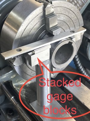
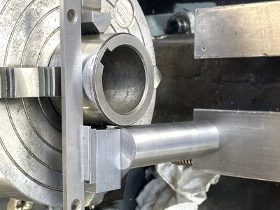
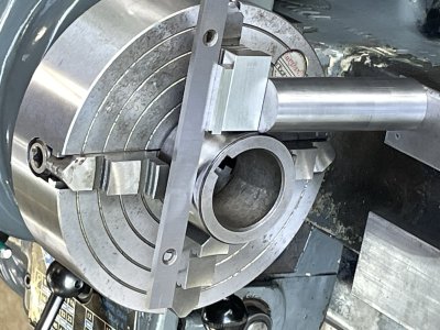
I used an old (but good condition) bushing in the 4 jaw, measured the diameter and then selected the approximate gage blocks to = half the bushing diameter. The set-up looked like this:
18A59716-66DA-496F-BA92-499441DFE855.jpeg
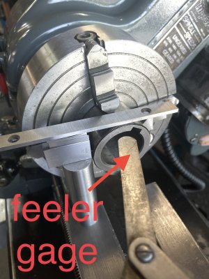
The horizontal parallel placed on both the top of the blocks and bushing shows that the height gage is still too tall. Nice thing here is that by using a feeler gage you can tell how much more to shorten the height gage.
B026736C-0D61-4DAA-A6BB-3D381E0F29A7.jpeg
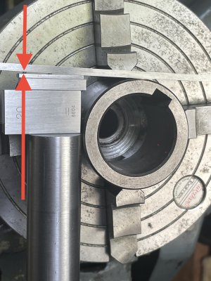
You can also see the gap (between arrows in next picture) to help zero in on the right gage height.
489E5973-EF16-4D2E-8522-B5E171BC6A31.jpeg
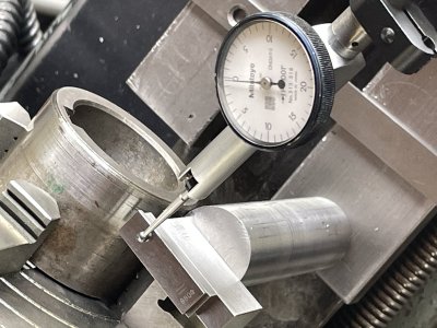
Here’s Joe Pie’s method - using a DTI to check that top of stacked gage blocks = top of the bushing. (I did both, but prefer the parallel across the top). F8B15320-12AC-49E5-93D2-2A2EB156E4CB.jpeg
Here’s the finished height gage, checked from both sides with a parallel3386F72B-FB5C-439F-87D1-849804E719BF.jpeg0EE5A327-C427-4A56-B8C8-0006B485681C.jpeg
 
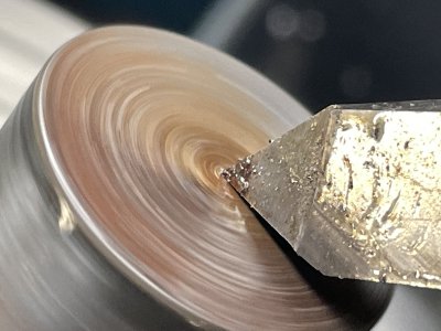
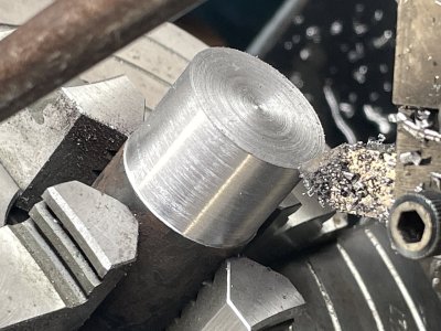
Fyf’s FIRST CHIPS! :-) :-)
I used the new height gage to set the cutter. I’d previously set this cutter on the center of a 1/16” drill bit (pics were posted above somewhere) but height gage showed that it was off! Off by quite a bit.
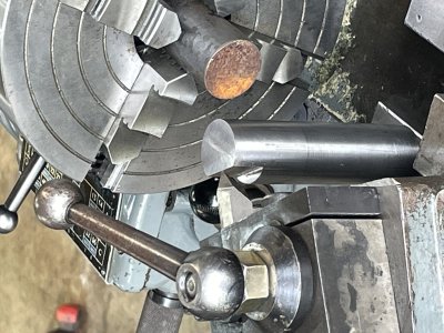
First cut was facing a rusty and uneven piece of 1” dia rod of mystery steel (just hot rolled i guess).
A93D61D8-1E82-432C-950B-70027073994C.jpeg
Next cut was to clean up the face This was a pretty big cut. Loved it - so very smooth, quiet and finished dead center. Thanks to the height gage.
A6362BB4-4BE4-4BF8-8CFE-6541658A6ED3.jpeg26EA3FDC-FCD2-43F2-9D19-4A14C93203F6.jpeg
Here’s using the QCGB to control lateral feed
CF648823-1BF8-4B92-8610-1A5E30ECEB2F.jpeg

Final results
FD1DBBB4-3823-460C-A422-3A5BA359F040.jpeg

BIG HAPPY FACE HERE :-)
 
We have an Edit deadline now?

Sorry I offended... OK, maybe not all that much... I don't speak in code. Spent almost thirty years working in an environment that sold toad-code as THE answer, when the Franco guys, in reality, were looking at the English side of the Tech Manuals, to figure out what they meant! (which is to say, the translations were a day-glo abortion, and Like the guy said, most of the money spent translating the Tech Manuals to being supposedly Bilingual, was wasted! Mostly because they invented a lot of new words for stuff that even the Franco's did not understand.
True story, they were some pretty decent folks to know. Despite the politics (and their complete ignorance, intended I am sure, of the actual history of this Country!). Most had no idea where the Canadians got their ambition to follow the Commonwealth!

Anyways.

But I note that there is no longer an option to edit any of my prior posts.
 
Last edited:
Please excuse - but i should have included this pic first.
Setup with height gage and the rusty piece of stock that is about to see the Myf cutter
View attachment 47676
Glad your lathe is working well, and equally glad that the height gage you made works! For now! LOL!

Try not to spit when it doesn't, if that time comes!
 
Regular members can only edit posts for a few moments. Premium members can delete and edit their own posts indefinitely.
I upgrade to Premium shortly after joining - so I never realized that editing privileges came with the upgrade. Similarly the upgrade allows me to add pictures to a PM. Again - I just thought that was available to everyone.
Point being - I suggest that administration should point these advantages out on the ‘membership upgrade page’.

CW
Same, on all counts!
 
I will endeavour to put something on the upgrade page.

The premium membership features pre-date me. But it's my understanding that the features were more of a way to say "thank you" than bait to donate.

There are not many.
1. Unlimited ability to edit and delete posts.
2. Ability to attach photos to PMs.
3. Access to a Premium Members Lounge - which isn't used much. (added by edit per CWret comment below)

All levels of upgrades get the same features.
 
Last edited:
Plus-

3. A very under utilized ‘Premium Members Lounge’

(Thanks! See edit above Susq)
 
Last edited by a moderator:
Been a while @CWret. That summer cottage of yours takes up waaaay too much of your time. I'm still waiting to see your first lathe project.....

Hard to believe you actually made your height standard on your mill.... Also impressed that you did that. But still, it really was a wasted opportunity....

GOYA GOYA Craig!
 
I'm still waiting to see your first lathe project
Well me too! - Soon maybe??

June to September have so many other things to do (rather than shop time). Plus the Boss has me on overtime getting ready for a pending reno and also earlier this summer came along another grand daughter - so the Myf didn’t get much attention. Although I am now putting the finishing touches on a new stand for it.
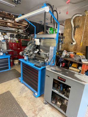
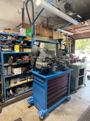
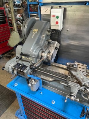
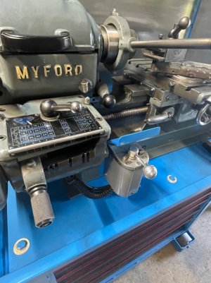
So here is a few pics (update) on my Myf and the stand.

Here is the original stand beside the new stand.
IMG_2236.jpeg
and from the other side
IMG_2233.jpeg
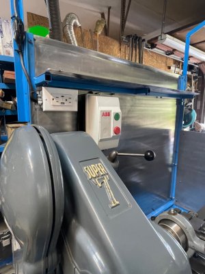
Since I relocated both the main power switch and the fwd/rev lever, there was a bit of electrical rewiring so i added an overhead LED light and a 110 outlet (which includes a USB port).
IMG_2234.jpegIMG_2237.jpeg
IMG_2235.jpeg
The new stand takes up about the same floor space as the original stand but has tons more storage. It is also much more robust. It weighs 420 lb (empty). I added a heavy frame to the top and to the bottom as well as beefed up the vertical corners. The steel wheels are rated at 1,000lb each. When I finally figure out where it is going to reside (final resting place in my small work space, then I won’t be using the wheels) I’ll block up a couple of the wheels to compensate for the sloped garage floor.

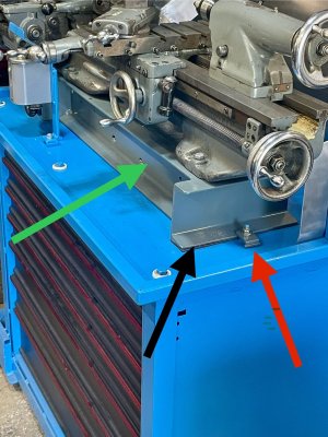
Between the lathe and the stand is a very ridged base. Here’s a pic of the base:
IMG_2239.jpeg
This base weighs 88 lb. It is comprised of 4” channels and 5/8 x 3” flat bar top and bottom - plus welded in 1.5” rods to fill the interior between the channels.
- green arrow is the base, black arrow showing the 1/8” rubber pad between the base and the stand, red arrow is the clip attachment for the stand to the base. (The clips have nylon locking nuts and are snug not tight)
I’ve not seen this approach before (please comment) but I plan to level the Myf to the base not the stand. The stand and the base are pretty much independent. (Keep in mind that Myfords are relatively small and are often used as a bench top lathe.)
- In pic below, to level the lathe I’ll be shimming the front and back bolt (on the left or right side of the bolt) until my test piece is not tapered.
IMG_2241.jpeg

As you can see Susq - that first lathe project is still a ways off.
 
Last edited:
Back
Top