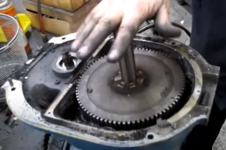
For those who haven't looked inside the head of a variable speed bridgeport... you can see below what you have to work with in terms of placing a magnet array and hall effect sensor. This is why I've leaning towards the quill mount route
View attachment 33993
Underneath the upper drive belt, pulley and then the brake shoe assembly you find this aluminum plate protecting the bull gears... It takes a lot of disassembly to get to this point. If your head does not need any work this is a task most people likely prefer not to undertake.
Here is the large bull gear itself
Now
@Susquatch was thinking of drilling the casing and inserting a hall sensor to read the gear teeth.
Since I'm going to be disassembling the head of our mill to rebuild it, I'm planning to investigate this option in detail despite the likelihood of rejecting it.
One immediate complication is that it appear that a sensor must be located right where the flange of the bull gear housing is located. This may be problematic because it looks like the flange is narrower than the width of the typical 12mm hall effect sensor housing that would have to pass thru the flange area. Additionally, the large bull gear changes height vertically, moving up or down to engage or disengage the small gear to the rear of the head as the speed range is changed from low to high gear.
This vertical movement may impact the sensor operation, therefore before I would select this sensor location I would want to test such a set-up to ensure reliable sensor triggering prior to undertaking any installation work.
Here is how I'd test this configuration:
First I'd measure the height of the bull gear position in both low and high speed setting in relation to a fixed reference point, and then calculate the bull gear's vertical offset in relation to the hall effect sensor for both high and low speed operation, as well as calculating the mid-point between the upper and lower heights.
Then I'd locate and mark that mid point plane on the inside of the bull gear housing, and hope it does not coincide with the top flange of the housing.
Then I'd remove the bull gear from the mill head and use it to construct a test apparatus, installing the bull gear on a mandrel held between vee blocks or similar so that the bull gear can rotate freely.
Then I'd rig a test stand to affix my sensor head to in order to position the sensor at the two offsets to the gear when the mill is running in low and high speed.
Then I'd power up the sensor and connect it to a oscilloscope to verify that the sensor triggers each time a gear tooth passes the read head. I'd reposition the test stand to calculate the maximum vertical and horizontal offsets where the sensor will trigger at the passing of each tooth. Based on this data I'd determine if the sensor head can be physically located in a position where is will work reliably in situ under both high and low speed operation.
Another potential issue is potential fouling of the sensor over time, since the grease packed in this housing gets filled with super fine metal particles which could impact the magnetic fields sufficiently to interfere with triggering the sensor reliably.