• Scam Alert. Members are reminded to NOT send money to buy anything. Don't buy things remote and have it shipped - go get it yourself, pay in person, and take your equipment with you. Scammers have burned people on this forum. Urgency, secrecy, excuses, selling for friend, newish members, FUD, are RED FLAGS. A video conference call is not adequate assurance. Face to face interactions are required. Please report suspicions to the forum admins. Stay Safe - anyone can get scammed.

Multi-machine tachometer and machining calculator

Is it going to be open source?
probably.

it was really only a project for our own personal machines and to have some to gift to a few people, but then we discussed the possibility of making it open source, and perhaps selling the completed boards only because my friend has the skills to make them up cheaply.

Really this was a brush up our skills in preparation for bigger and better things
 
I have designed a case with nice rounded corners, but in hind sight I think a flat front, with an inset lid that can accept a piece of acrylic better option since I'd not need to design in a front opening for the LCD screen. Better protection for the screen and interior components.

Or maybe clear SLA resin can be polished to be fully transparent? Then I'd be able to retain the rounded design, and only need to glue in inserts instead of using heat staked inserts. I sortta like the look being able to see the components

1677958077202.webp
 
Frankly, I'd pay extra for one that I could see the components. I think that's very cool!

I'm going to have some test propellers made in SLA resin, I'll get a few cases made at the same time. Formlabs tells me that the parts can easily be sanded and polished to be optically clear.
 
V2 of the hardware has landed.

Well, at least the boards arrived at our Canadian "manufacturing facility" and have been assembled. So it is almost time for field testing with the v1 software.

PXL_20230318_182617005.jpg


I'm still working, as my schedule allows, to compile data tables for the materials and cutter properties to be able to go live with V2 software.

I admit that I don't know enough to decide without consulting other more experienced machinists what materials I can/should omit from tables, or just lump into a group of similar materials. I know sites like the little machine shop have chosen to focus on very limited materials in their data tables because they know their user base only uses a handful of materials on a regular basis.

In just steel alone I have charts for 3 classes of non-alloyed steels, 1 low alloyed steels, 1 tool steel & high alloy steels, 5 classes of stainless steel and 6 classes of cast iron.

But I suspect I could omit all these non-alloyed steels with between 0.1-0.25% carbon. Raise your hand if you have ever used one of the steels in this example.
10PbF2
A27 65.35
A33
A34-2
A34-2NE
A515.65
A570.36
A573
A633

How about these non alloyed 0.26-0.50%carbon steels?

20AP
22CMSD4
3135
3415
35NCD14
A516
A516G60
A516G70
A537
A570
A572
A572.60
A70-2
A738
C25
1108
1112
1140
1144
1151
1213
1215
12L13
12L14
 
V2 of the hardware has landed.

Well, at least the boards arrived at our Canadian "manufacturing facility" and have been assembled. So it is almost time for field testing with the v1 software.

View attachment 32567

I'm still working, as my schedule allows, to compile data tables for the materials and cutter properties to be able to go live with V2 software.

I admit that I don't know enough to decide without consulting other more experienced machinists what materials I can/should omit from tables, or just lump into a group of similar materials. I know sites like the little machine shop have chosen to focus on very limited materials in their data tables because they know their user base only uses a handful of materials on a regular basis.

In just steel alone I have charts for 3 classes of non-alloyed steels, 1 low alloyed steels, 1 tool steel & high alloy steels, 5 classes of stainless steel and 6 classes of cast iron.

But I suspect I could omit all these non-alloyed steels with between 0.1-0.25% carbon. Raise your hand if you have ever used one of the steels in this example.
10PbF2
A27 65.35
A33
A34-2
A34-2NE
A515.65
A570.36
A573
A633

How about these non alloyed 0.26-0.50%carbon steels?

20AP
22CMSD4
3135
3415
35NCD14
A516
A516G60
A516G70
A537
A570
A572
A572.60
A70-2
A738
C25
1108
1112
1140
1144
1151
1213
1215
12L13
12L14

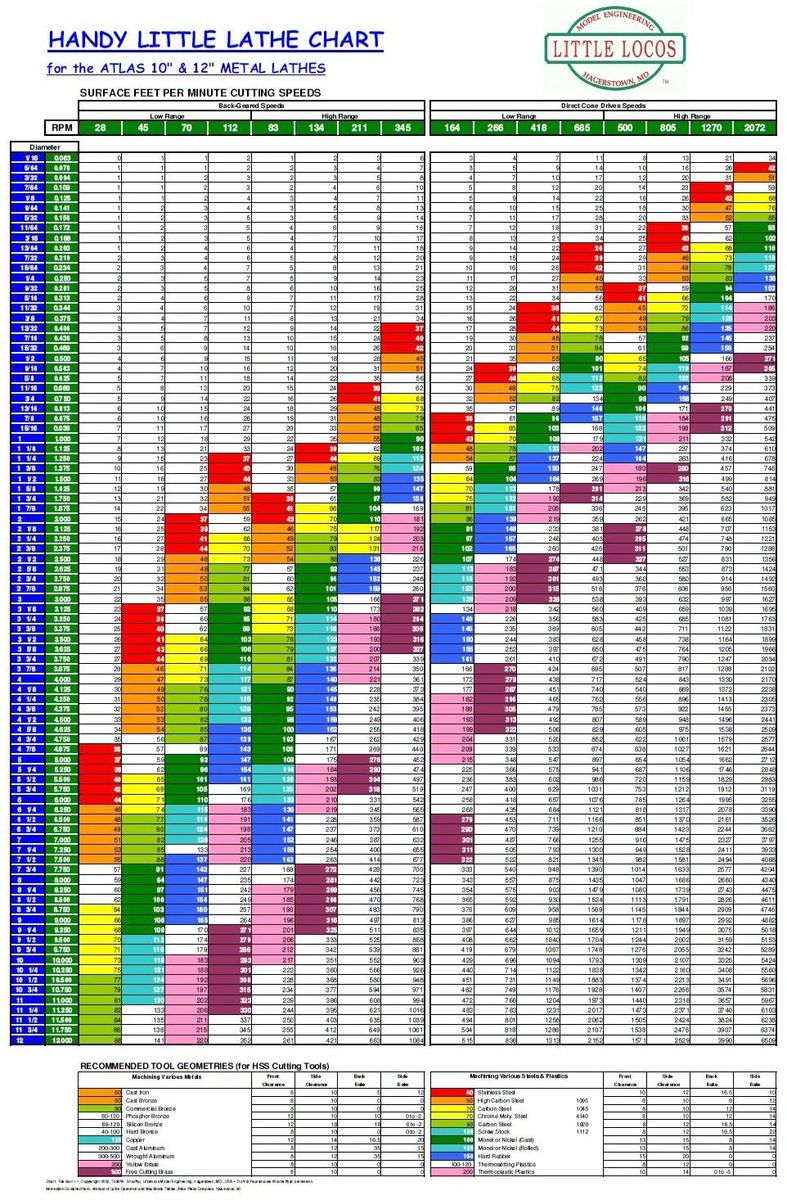
I tend not to know what my metal is with any regularity. I mostly use mystery metal.

That's why I really like this chart. I bought one and attached it to the wall behind my lathe.

Here is a link to one of their charts.


Here is a photo

Screenshot_20230320_142117_Chrome.jpg


Notice the metals are not specific, but rather are somewhat classified. I think that might be an easier way to categorize materials than by individual metal designations.

Here are fuzzy versions of the categories

Screenshot_20230320_141958_Chrome.jpg


Screenshot_20230320_141933_Chrome.jpg

My recommendation would be a choice between using categories like these or specific metals.

But if I couldn't have both, I'd go for categories only since one can always easily identify the category for a specific metal but not so easily find another material the same as whatever you want to use.
 
I'm debating if I need to break out the 6 main ISO materials categories; Steel, Stainless Steel, Cast Iron, Nonferrous, Superalloys and Hardened Steel into subgroups. Our method of scrolling means we can zip thru a long list very quickly to select a material with no real issues, and I can't see a reason you'd need to know what sub group a particular material belongs to when you are only using the table to populate the recommended metric and imperial speed rates for Turning, Parting, Grooving, Milling, and Drilling.
 
I tend not to know what my metal is with any regularity. I mostly use mystery metal.

That's why I really like this chart. I bought one and attached it to the wall behind my lathe.

Here is a link to one of their charts.


Here is a photo

View attachment 32572

Notice the metals are not specific, but rather are somewhat classified. I think that might be an easier way to categorize materials than by individual metal designations.

Here are fuzzy versions of the categories

View attachment 32574

View attachment 32575
My recommendation would be a choice between using categories like these or specific metals.

But if I couldn't have both, I'd go for categories only since one can always easily identify the category for a specific metal but not so easily find another material the same as whatever you want to use.
That table is great, I have a very similar chart with the ISO colours too. It basically combines the condensed data for the 6 major materials classes into a single chart. I can create one large single look up table like this to use to to select the material properties data, but we are trying to optimize the methodology to use the single encoder wheel data selection method.

So I'm debating what will provide the optimal, fastest data selection that is also highly intuitive. I'm thinking 6 look up tables based on the 6 materials types. In order to condense the data I an trying to figure out what obscure options I can leave out. I'm getting that I could omit many of them.

OF course, I'm the same as you. I often have material I only can guess at the main material category ie some sort of mild steel for instance. The first entries on the look up table will say "generic mild steel", or "generic aluminium" before going on to list specific numbered material lists like this:


1006
1008
1010
1015
1020
1022
1025
1035
1039
1040
1043
1045
1049
1050
1055
1060
1070
1080
1086
1108
1112
1140
1144
1151
1213
1215
1330
1335

This table above can be rotated thru in 2 seconds. A single table would need to be spun thru more slowly and take too long I think hence the 6 tables.

But I also question if there is a benefit to breaking down the data further into sub groups more tables. I guess we should test with 6 categories and see if we need to break them down later.
 
That table is great, I have a very similar chart with the ISO colours too. It basically combines the condensed data for the 6 major materials classes into a single chart. I can create one large single look up table like this to use to to select the material properties data, but we are trying to optimize the methodology to use the single encoder wheel data selection method.

I am away right now. When I get home I'll take closeups of the categories on my chart for you.
 
I am away right now. When I get home I'll take closeups of the categories for you.
Great.

Under the set-up mode I can add choice of "simple or advanced modes" which will switch between a condensed table of 22 metals like yours or the multiple tables based on larger selection with 6 materials categories for metals... or and then woods and plastics
 
Is it going to be open source?

To comment further on our plans I believe that we're considering using the Creative Commons license class "Attribution-Non Commercial 4.0 International (CC BY-NC 4.0)".

It is my understanding that with that license we can share pcb schematics, and software code to individuals who wish to make their own devices for their personal non-commercial use. They're free to modify any of the shared materials provided that they of course meet the license terms in regard to atribution.

Our intent it to make the tool readily available to individuals. Of course they wont be able to order their own boards etc as cheaply as they could by from us since we'd be ordering and assembling our devices in bulk batches.
 
Sorry, I forgot about doing that. Getting a tropical rainstorm here with tornado warnings. Never did like getting wet....
Susquatch must be in same family tree as cats.

Yeah we had storm here too for hours, freaking out the dog.

But we avoid tornado alley mostly. My grandma's house was relocated off it's foundation when I was an infant... it was only about 100 km SW of you.
 
Susquatch must be in same family tree as cats.

Yeah we had storm here too for hours, freaking out the dog.

But we avoid tornado alley mostly. My grandma's house was relocated off it's foundation when I was an infant... it was only about 100 km SW of you.
The things you remember when you have a good reference or two. It was an F4 tornado that killed 18 people and injured tons of people. It occurred just days before my sisters birthday party was supposed to be held at my grandmas Apr 12, 1965
 
It is time to consider mounting options for the Mill

The goal is to design a simple to make and install the sensor mount and magnet array, which should provide a fairly universal method for most mill users.

Our bridgeport mill has a pretty healthy 5" travel so I think I can spare 1/4 to 3/8" of travel to make a ring clamp to which the sensor may be attached. The clamp of course will prevent the quill from fully retracting, which in turn may place an axial load on the ring clamp. The ring clamp design will need to provide sufficient strength to resist these axial forces while having a narrow profile.

The location of the clamp is shown in yellow.

The magnet array will mount just below this on the exposed ~1" length of the spindle in a manner similar to which I attached the magnet array to the lathe.

1681662408824.webp


Thoughts?

Will this work with most mills, or would it eliminate too much travel on smaller mills?
 
My concern would be the wires from the sensors getting tangled up in something. Might not be a problem when the quill is retracted, but as the quill extends further out of the housing, the wires need enough slack to follow the quill down.

I would try and mount the sensors on top of the head. Perhaps as part of a draw bar extension sleeve?

Or integrate the sensor somehow inside the head? I know, now it gets more complicated…
 
Back
Top