• Scam Alert. Members are reminded to NOT send money to buy anything. Don't buy things remote and have it shipped - go get it yourself, pay in person, and take your equipment with you. Scammers have burned people on this forum. Urgency, secrecy, excuses, selling for friend, newish members, FUD, are RED FLAGS. A video conference call is not adequate assurance. Face to face interactions are required. Please report suspicions to the forum admins. Stay Safe - anyone can get scammed.

Mikes shop activities

Mike R

Super User
Premium Member
Here's a list of all the current activities. Like others, I jump around too much to have a dedicated thread for 1 activity, so I'll toss them together in this word salad of all things going on in my hobby shop.

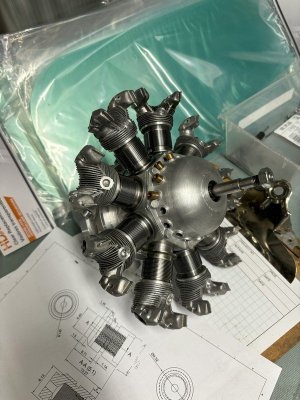
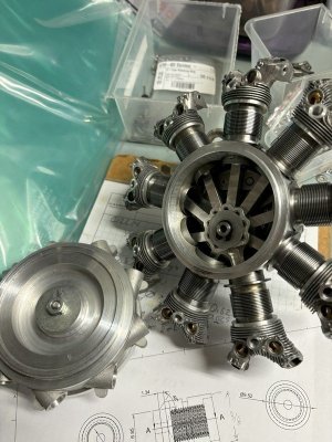
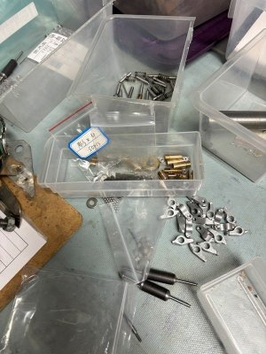
The longest "active" project is the radial. Started it 10+ years ago. Didn't know squat about machining, cnc, etc. Been a learning experience. Lots of parts and need to remake a lot of them, but its getting closer. Optimistically - maybe a year or 2?

Next on the list is the B1 Springbok 5" gauge live steam locomotive. Bought as a chassis running on air. I've so far built the tender body 80%, and soldered up the insides of the boiler. Next up is boiler assembly, going to be a big job and waiting on spring weather to have a go.

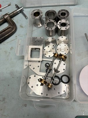
After that is a Worthington duplex steam pump. I got distracted building the B1 boiler and needed some machining time, and the radial was at a difficult place for me so I started something new. This one is about 90% done. I may actually finish it...its all small but time consuming parts left (tube fittings, check valves and some silver soldering.)

Then its mostly either new things I shouldn't start yet, or tool / workshop fixes / upgrades etc.

In the list of things that I've started the mental exercises but really should not start until the above are done:

Gauge 1 (45mm between the rails) live steam "Green Arrow" locomotive (2-6-2) - fair amount of CAD done on parts I'd CNC
Some design work on making a functional direct injection diesel in small scale (~22cc - 28mm diam piston x 35mm stroke) - because I like a challenge...
I also have castings for a 1/4 scale Wright Whirlwind 9 cylinder for when I'm bored
A 3.5" gauge Britannia Duchess part built chassis as received by my dad, who gave it to me to finish as he's smart enough to know when he has too many things to do.

Hopefully I'll be sharing some progress and wins along the way.
And pictures, always pictures. After this week at work I have had it reinforced in my head that nobody reads words
radial-back_CHMW.jpgradial-bits_CHMW.jpgradial-front_CHMW.jpgworthington-pump-parts_CHMW.jpg.
 
Last edited:
Which radial is that ?
Guess you didn't think a three or a five cylinder might be a gooder starting project. ;)
 
Which radial is that ?
Guess you didn't think a three or a five cylinder might be a gooder starting project. ;)
Yeah, I know, one of the more difficult engines out there to build..
Its a Pratt and Whitney Wasp Jr. (R-985) in 1/6th scale. If being 9 cylinders wasn't enough its a smaller scale than most making it more like watch making at times...
 
Thanks, I think it looks nice cause alot of the glamorous parts are castings I bought (cylinder head and front crankcase). Doing my best to not mess them up as they are no longer available. I'd love to get one of the heads 3d scanned so I could make a new one, drawing it is such a pain...
 
Its a Pratt and Whitney Wasp Jr. (R-985) in 1/6th scale.
Nice. I think I've seen your Wasp pics on one of the ME forums. What's the history of yours? When did you get the parts? Were the plans 'serviceable'? (I seem to recall you did a CAD re-do).
I think Bruce Satra was one of the the Wasp casting guru's, but I also seem to recall others have modelled the Wasp in other flavors. I wonder what became of his wax casting dies & such?

Recently I was digging in my storage box for some obscure magazine back issue & found a handwritten reply letter from Bruce when I was contemplating his single as a starter project. I think I had just got my lathe around then & didn't know which end was up, never mind taking on a jewelry casting. So I passed. Probably made sense at the time, but OTOH it would be nice to have a small piece of model engineering history. Well I hope you keep pursuing yours. I am familiar with the 'its almost done' syndrome, there is a lot of work in those little buggers.

 
Yeah, I know, one of the more difficult engines out there to build..
Its a Pratt and Whitney Wasp Jr. (R-985) in 1/6th scale. If being 9 cylinders wasn't enough its a smaller scale than most making it more like watch making at times...
Cool, only familiar with the 1:1 scale and those are great. Very impressive job Mike.
 
Todays update: just a few house keeping items and spending more money on a new mini project.
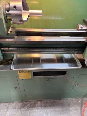
I found these large baking pans at Costco for $9 each, and they are the cheapest way I could find to get a piece of sheet metal that size. Anyways, I bought 2, 1 went under the mini mill cause it leaks like a sieve, and the other I wanted to use on my horizontal bandsaw as it piddles all over like a 2 year old boy potty training....
But it fits just so nicely under the lathe it might actually make cleaning it up a task that gets done and not just thought about.
I could just go buy another for the bandsaw.
IMG_1938_CHMW.jpg

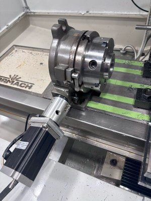
The other thing is I wanted to get back to having a 4th axis on the mill. When I sold my DIY mill I kept my 6" rotary table that I had adapted a stepper motor to, and it has an adapter to my D1-4 chucks that makes swapping a part from the lathe to the mill (and back again) an easy task. Only issue is that I found the stepper motor was just not strong enough to move the rotary at a good speed without loosing steps. Keeping the rpm's low (~3 or 4 maybe - like 900 or 1500 degrees per minute) it was reliable, but that was painful to do, especially as I hadn't figure out how to go from 355 degrees to 0 the "short way" in the software, and if I'd gone around a few times I had to unwind it as far as the software was concerned (doesn't have position feedback).
IMG_1960_CHMW.jpg

Anyways, long intro to I spent money on a new closed loop stepper motor and driver that ought to be able to move this at a much faster pace, should arrive Friday.
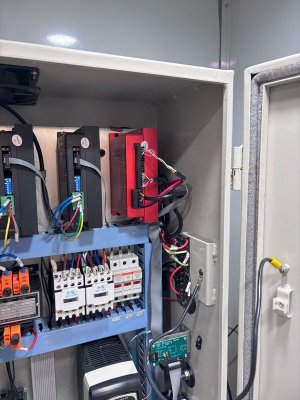
I justified it by telling myself I needed to buy a driver anyways. Hopefully its a quick project. The cabinet has space, it has wiring connections to the control board already, and has dedicated terminals for DC power for the drive.
IMG_1962_CHMW.jpg
1743562982686.png


Tormach already have a configuration setup for 4th axis that I just need to use. The one thing I will need to do is make a new adapter for the larger stepper motor (actual metal working).
The only thing I'm on the fence about is maybe mounting the motor in back of the rotary table and connecting to the shaft with a pair of pulleys. That would be so that I can mount it on either end of the table. As it is now, the motor sticks out too much to mount on the right side of the table - it will interfere with the column and cabinet.
That would prevent the table being used vertically. I don't need it for rotating things vertically as the CNC can do that, but I did find it handy to use as a way of having the chuck to hold round things vertically (think pocket inside a piston). decisions...
 
Todays update: just a few house keeping items and spending more money on a new mini project.
I found these large baking pans at Costco for $9 each, and they are the cheapest way I could find to get a piece of sheet metal that size. Anyways, I bought 2, 1 went under the mini mill cause it leaks like a sieve, and the other I wanted to use on my horizontal bandsaw as it piddles all over like a 2 year old boy potty training....
But it fits just so nicely under the lathe it might actually make cleaning it up a task that gets done and not just thought about.
I could just go buy another for the bandsaw.
View attachment 62557

The other thing is I wanted to get back to having a 4th axis on the mill. When I sold my DIY mill I kept my 6" rotary table that I had adapted a stepper motor to, and it has an adapter to my D1-4 chucks that makes swapping a part from the lathe to the mill (and back again) an easy task. Only issue is that I found the stepper motor was just not strong enough to move the rotary at a good speed without loosing steps. Keeping the rpm's low (~3 or 4 maybe - like 900 or 1500 degrees per minute) it was reliable, but that was painful to do, especially as I hadn't figure out how to go from 355 degrees to 0 the "short way" in the software, and if I'd gone around a few times I had to unwind it as far as the software was concerned (doesn't have position feedback).
View attachment 62558

Anyways, long intro to I spent money on a new closed loop stepper motor and driver that ought to be able to move this at a much faster pace, should arrive Friday.
I justified it by telling myself I needed to buy a driver anyways. Hopefully its a quick project. The cabinet has space, it has wiring connections to the control board already, and has dedicated terminals for DC power for the drive.
View attachment 62559 View attachment 62560

Tormach already have a configuration setup for 4th axis that I just need to use. The one thing I will need to do is make a new adapter for the larger stepper motor (actual metal working).
The only thing I'm on the fence about is maybe mounting the motor in back of the rotary table and connecting to the shaft with a pair of pulleys. That would be so that I can mount it on either end of the table. As it is now, the motor sticks out too much to mount on the right side of the table - it will interfere with the column and cabinet.
That would prevent the table being used vertically. I don't need it for rotating things vertically as the CNC can do that, but I did find it handy to use as a way of having the chuck to hold round things vertically (think pocket inside a piston). decisions...
I would mount on the back with pulleys. I'd also set it up so you could do 1:2 so you can still stay in the high torque end of the stepper motor and run the table at twice the speed. So mount the motor high enough so that if you have a 20T pulley on the drive you can still mount a 40T pulley on the motor.
 
If they are the same ones I bought a few years ago they are aluminum I bought 6 of them I even have one under the compressor drain valve.
 
I would mount on the back with pulleys. I'd also set it up so you could do 1:2 so you can still stay in the high torque end of the stepper motor and run the table at twice the speed. So mount the motor high enough so that if you have a 20T pulley on the drive you can still mount a 40T pulley on the motor.
I'm going to doodle tonight and see what I can come up with, just found a rather simply modeled 6" vertex rotary table on Grabcad that I'll check against my table, and I'll see what I come up with. I have a crazy thought that I might even be able to make the motor mount swivel around so that the motor is off to the side when the table is laid on its back...
 
Well, this project had me fall into the trap of perfection is the enemy of good, or better vs good enough, and starting with a bad assumption...

My head was still in dividing head land (just picked up an Elliott dividing head) while trying to do the math for the rotary table. 40:1 ratio I was thinking for input to output. Correct for a dividing head (but not for a rotary table as we'll see later).

Anyways, on the theme of achieving perfection, I was thinking, with 40:1 input ratio, its pretty hard to get a 200 step / rev stepper motor to have an even # of steps per degree and the perfectionist in me grabbed onto that and would not let go...(for no good reason)
So after much thought, I realized that I was already planning on a geared change from the stepper to the input and could use that to make up the difference to get the steps per degree back to a whole number. Easy peasy - a few hours later I figured out that the ratio of motor steps/ rev was the key and by choosing a reduction / step up ratio that matched I could get to even # of steps per degree. So instead of 40:20 pulleys I needed 36: 20. Nice and easy - pretty close to the originally planned ratio. Problem was I had already ordered pulleys from AliExpress.
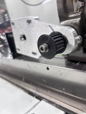
Next brain wave - I now own a 3D printer. Why didn't I just print them in the first place? An hour or 2 later I had some 3D printed pulleys.
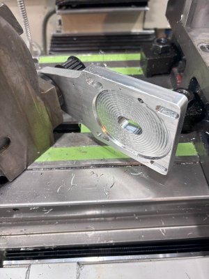
Next issue was the mounting plate didn't allow enough adjustment for the smaller 36T pulley. Just enlarge the slots and recess and another hour gone...

Now I put it all together and its getting late. I am configuring PathPilot and I cannot for the life of me understand why the math is wrong. Really wrong (3x or more.) BTW - each change I had to reboot to make it effective (need to learn a shortcut for that if I'm going to play like this again).

Many head scratches later, I check the rotary table and realize its 90 input turns to 1 output revolution.

Redo math, now can't get even # of steps per degree. Second face palm in as many minutes, the pulley ratio doesn't need to be 1.8:1 anymore.
If I go back to 40:20 pulleys, then the math works out nicely for even steps per degree.
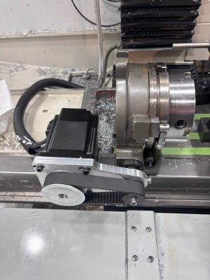
Even better, by picking a micro stepping of 4000 per motor rev - the step scale (steps per degree) works out to 500 - exactly the same as pre-programmed in PathPilot for Tormachs 6" and 8" rotary tables - so no need for any customization and no worries if I update Pathpilot, however I have choosen to modify the max angular velocity to 6000deg/min (16.6rpm) as it seems reliable at that - higher was behaving weird. This is about 5 times faster than the previous iteration so I'm happy.

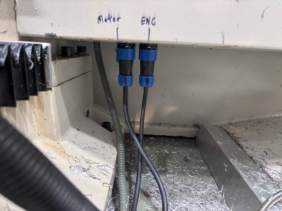
With all that - here is the end result. Still need to make a belt cover and motor cover with cable strain relief, but already useable as is.
And its much faster than the previous stepper motor.
Lastly - as a sanity check - I wanted to make sure that 500 steps per degree was enough resolution. Its only 1.3888 steps per minute and not even close to doing seconds.
This is where the reasonable and practical side of me finally showed up.
This is a 6" table, and can realistically swing a max 8" diameter piece in the horizontal position over the table. Circumference of 8" is ~25.1" 500 steps per degree x 360 = 180000 steps per rev. 180000/25.1 = 7171 steps per inch or about 7 steps per thou at max diameter. Seems much better than I will ever really be able to achieve in real life.

Moral(s) of the story - remember what you are really trying to achieve, when better is the enemy of good enough. Good enough is not settling, it means you've achieved your goal without the wasted effort of achieving the "better" that will not be realized as a benefit.
Double check your assumptions
Remember all the tools you own before buying stuff
...
on to the next project.

IMG_2074_CHMW.jpgIMG_2065_CHMW.jpgIMG_2066_CHMW.jpgIMG_2069_CHMW.jpgIMG_2072_CHMW.jpg
 
Well, this project had me fall into the trap of perfection is the enemy of good, or better vs good enough, and starting with a bad assumption...

My head was still in dividing head land (just picked up an Elliott dividing head) while trying to do the math for the rotary table. 40:1 ratio I was thinking for input to output. Correct for a dividing head (but not for a rotary table as we'll see later).

Anyways, on the theme of achieving perfection, I was thinking, with 40:1 input ratio, its pretty hard to get a 200 step / rev stepper motor to have an even # of steps per degree and the perfectionist in me grabbed onto that and would not let go...(for no good reason)
So after much thought, I realized that I was already planning on a geared change from the stepper to the input and could use that to make up the difference to get the steps per degree back to a whole number. Easy peasy - a few hours later I figured out that the ratio of motor steps/ rev was the key and by choosing a reduction / step up ratio that matched I could get to even # of steps per degree. So instead of 40:20 pulleys I needed 36: 20. Nice and easy - pretty close to the originally planned ratio. Problem was I had already ordered pulleys from AliExpress.
Next brain wave - I now own a 3D printer. Why didn't I just print them in the first place? An hour or 2 later I had some 3D printed pulleys.
Next issue was the mounting plate didn't allow enough adjustment for the smaller 36T pulley. Just enlarge the slots and recess and another hour gone...

Now I put it all together and its getting late. I am configuring PathPilot and I cannot for the life of me understand why the math is wrong. Really wrong (3x or more.) BTW - each change I had to reboot to make it effective (need to learn a shortcut for that if I'm going to play like this again).

Many head scratches later, I check the rotary table and realize its 90 input turns to 1 output revolution.

Redo math, now can't get even # of steps per degree. Second face palm in as many minutes, the pulley ratio doesn't need to be 1.8:1 anymore.
If I go back to 40:20 pulleys, then the math works out nicely for even steps per degree.
Even better, by picking a micro stepping of 4000 per motor rev - the step scale (steps per degree) works out to 500 - exactly the same as pre-programmed in PathPilot for Tormachs 6" and 8" rotary tables - so no need for any customization and no worries if I update Pathpilot, however I have choosen to modify the max angular velocity to 6000deg/min (16.6rpm) as it seems reliable at that - higher was behaving weird. This is about 5 times faster than the previous iteration so I'm happy.

With all that - here is the end result. Still need to make a belt cover and motor cover with cable strain relief, but already useable as is.
And its much faster than the previous stepper motor.
Lastly - as a sanity check - I wanted to make sure that 500 steps per degree was enough resolution. Its only 1.3888 steps per minute and not even close to doing seconds.
This is where the reasonable and practical side of me finally showed up.
This is a 6" table, and can realistically swing a max 8" diameter piece in the horizontal position over the table. Circumference of 8" is ~25.1" 500 steps per degree x 360 = 180000 steps per rev. 180000/25.1 = 7171 steps per inch or about 7 steps per thou at max diameter. Seems much better than I will ever really be able to achieve in real life.

Moral(s) of the story - remember what you are really trying to achieve, when better is the enemy of good enough. Good enough is not settling, it means you've achieved your goal without the wasted effort of achieving the "better" that will not be realized as a benefit.
Double check your assumptions
Remember all the tools you own before buying stuff
...
on to the next project.

View attachment 63358View attachment 63360View attachment 63361View attachment 63362View attachment 63363
Nice. You’ve given me some ideas for converting my rotary table into a 4th axis. How are you managing backlash?
 
In general I don't control backlash, as I primarily use(d) the table as an indexer and not a true 4th axis. I don't have access to software that can generate 4 axis simultaneous CAM. My uses are like you would use a collet block, or for gear cutting, all moves are in the same rotation direction.
I probably could try and add backlash comp, but my experience is that its different depending on where in the rotation you are, and that means mapping....way too much effort for a cheap project that will never be that precise.
I guess I could probably use it for rotary engraving, then I'd need to figure out the average backlash at least.
 
Well, this project had me fall into the trap of perfection is the enemy of good, or better vs good enough, and starting with a bad assumption...

My head was still in dividing head land (just picked up an Elliott dividing head) while trying to do the math for the rotary table. 40:1 ratio I was thinking for input to output. Correct for a dividing head (but not for a rotary table as we'll see later).

Anyways, on the theme of achieving perfection, I was thinking, with 40:1 input ratio, its pretty hard to get a 200 step / rev stepper motor to have an even # of steps per degree and the perfectionist in me grabbed onto that and would not let go...(for no good reason)
So after much thought, I realized that I was already planning on a geared change from the stepper to the input and could use that to make up the difference to get the steps per degree back to a whole number. Easy peasy - a few hours later I figured out that the ratio of motor steps/ rev was the key and by choosing a reduction / step up ratio that matched I could get to even # of steps per degree. So instead of 40:20 pulleys I needed 36: 20. Nice and easy - pretty close to the originally planned ratio. Problem was I had already ordered pulleys from AliExpress.
Next brain wave - I now own a 3D printer. Why didn't I just print them in the first place? An hour or 2 later I had some 3D printed pulleys.
Next issue was the mounting plate didn't allow enough adjustment for the smaller 36T pulley. Just enlarge the slots and recess and another hour gone...

Now I put it all together and its getting late. I am configuring PathPilot and I cannot for the life of me understand why the math is wrong. Really wrong (3x or more.) BTW - each change I had to reboot to make it effective (need to learn a shortcut for that if I'm going to play like this again).

Many head scratches later, I check the rotary table and realize its 90 input turns to 1 output revolution.

Redo math, now can't get even # of steps per degree. Second face palm in as many minutes, the pulley ratio doesn't need to be 1.8:1 anymore.
If I go back to 40:20 pulleys, then the math works out nicely for even steps per degree.
Even better, by picking a micro stepping of 4000 per motor rev - the step scale (steps per degree) works out to 500 - exactly the same as pre-programmed in PathPilot for Tormachs 6" and 8" rotary tables - so no need for any customization and no worries if I update Pathpilot, however I have choosen to modify the max angular velocity to 6000deg/min (16.6rpm) as it seems reliable at that - higher was behaving weird. This is about 5 times faster than the previous iteration so I'm happy.

With all that - here is the end result. Still need to make a belt cover and motor cover with cable strain relief, but already useable as is.
And its much faster than the previous stepper motor.
Lastly - as a sanity check - I wanted to make sure that 500 steps per degree was enough resolution. Its only 1.3888 steps per minute and not even close to doing seconds.
This is where the reasonable and practical side of me finally showed up.
This is a 6" table, and can realistically swing a max 8" diameter piece in the horizontal position over the table. Circumference of 8" is ~25.1" 500 steps per degree x 360 = 180000 steps per rev. 180000/25.1 = 7171 steps per inch or about 7 steps per thou at max diameter. Seems much better than I will ever really be able to achieve in real life.

Moral(s) of the story - remember what you are really trying to achieve, when better is the enemy of good enough. Good enough is not settling, it means you've achieved your goal without the wasted effort of achieving the "better" that will not be realized as a benefit.
Double check your assumptions
Remember all the tools you own before buying stuff
...
on to the next project.

View attachment 63358View attachment 63360View attachment 63361View attachment 63362View attachment 63363
Oh gawd. You described my thought processes and methods. Scary.
 
Back
Top