• Scam Alert. Members are reminded to NOT send money to buy anything. Don't buy things remote and have it shipped - go get it yourself, pay in person, and take your equipment with you. Scammers have burned people on this forum. Urgency, secrecy, excuses, selling for friend, newish members, FUD, are RED FLAGS. A video conference call is not adequate assurance. Face to face interactions are required. Please report suspicions to the forum admins. Stay Safe - anyone can get scammed.

Metal lathe options

I found the motor mount behind the control box. The two bolts that hold the motor were not tight and were sitting in the middle of the mount. I pulled the motor to the bottom of the mount and made sure the nuts were tight. It actually isn't necessary to remove the back plate that covers the gears, the motor mount is easily accessible by removing the control box.
Good. As I recall, those motor securing bolts are just run into threaded holes in the (thin) motor shell. Some lathes have a 'positioning' bolt as well, which pushes the motor downwards, away from the ways. Next time you are poking around the back of the lathe you can take a look.
 
The accusize HSS is M35 HSS. M35 is an older HSS with some cobalt added to it. M4 is a newer steel with more wear resistance and it's not all that hard to get as a foot of 1/4 1" flat bar which would be enough for four tools. I'm thinking of making some tools out of 1/4 M4 in its annealed state and heat treat it to its top hardness.

I think maybe you are over thinking this. M35 blanks from Amazon or Accusize or or or ..... will all work just fine once your tool geometry is right. The worst that will happen is the need to resharpen them more often. In 40 years I've never worn one out. I just keep resharpening them or grinding new profiles. I only just recently got into using inserts in any major way. Most of my original HSS didn't even have any cobalt in it at all.

Some time at the grinding wheel learning what works will pay bigger dividends than worrying about the kind of HSS you use.

The biggest problem I see with new lathe operators is a fundamental misunderstanding of how the cutting process works. They assume that cutting takes place toward the lathe chuck. And some does. But very little. The vast majority of the cutting takes place around the circumference of the work - like peeling a spinning apple. It is the top of the tool that cuts, not the sides. The sides must all provide clearance so they don't rub - which is what your first experience was all about.

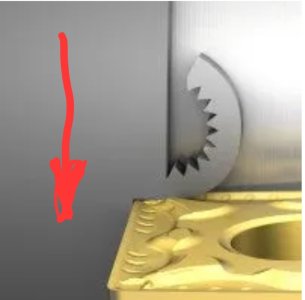
You will find a plethora of photographs and drawings on the Internet about how a tool cuts. Most of them are wrong. Here is a Sandvik photo of how the tool really cuts. It's not what you might think.

Screenshot_20240111_094333_Chrome.jpg

Notice that the work is rotating down (RED ARROW) against a more or less stationary tool. The tool isn't really cutting, it's actually more like plowing.

The tool does advance toward the headstock at the feed rate, but the majority of the force from the tool is PUSHING INWARD toward the center of the part which peels and buckles the chip off of the part, like peeling the Peel off of a spinning apple.

If you imagine the tool plowing along, you can immediately see the importance of relief on the faces of the tool that are adjacent to the part. You want the tool to cut (gouge) on the front and side top edge and buckle the work chip away from the parent part with the top of the tool. You don't want the tool to rub on the work at the front or the side.

This process is the same for carbide inserts or HSS.
 
I think maybe you are over thinking this. M35 blanks from Amazon or Accusize or or or ..... will all work just fine once your tool geometry is right. The worst that will happen is the need to resharpen them more often. In 40 years I've never worn one out. I just keep resharpening them or grinding new profiles. I only just recently got into using inserts in any major way. Most of my original HSS didn't even have any cobalt in it at all.

Some time at the grinding wheel learning what works will pay bigger dividends than worrying about the kind of HSS you use.

The biggest problem I see with new lathe operators is a fundamental misunderstanding of how the cutting process works. They assume that cutting takes place toward the lathe chuck. And some does. But very little. The vast majority of the cutting takes place around the circumference of the work - like peeling a spinning apple. It is the top of the tool that cuts, not the sides. The sides must all provide clearance so they don't rub - which is what your first experience was all about.

You will find a plethora of photographs and drawings on the Internet about how a tool cuts. Most of them are wrong. Here is a Sandvik photo of how the tool really cuts. It's not what you might think.

View attachment 42782

Notice that the work is rotating down (RED ARROW) against a more or less stationary tool. The tool isn't really cutting, it's actually more like plowing.

The tool does advance toward the headstock at the feed rate, but the majority of the force from the tool is PUSHING INWARD toward the center of the part which peels and buckles the chip off of the part, like peeling the Peel off of a spinning apple.

If you imagine the tool plowing along, you can immediately see the importance of relief on the faces of the tool that are adjacent to the part. You want the tool to cut (gouge) on the front and side top edge and buckle the work chip away from the parent part with the top of the tool. You don't want the tool to rub on the work at the front or the side.

This process is the same for carbide inserts or HSS.
It is true that edge geometry makes more of a difference in cutting ability thn metallurgy, but when your cutting hard metals the tool needs to have higher hardness than the metal you are cutting. The edge retention of the tool steel will also effect how well it can hold an edge that is fine/acute enough to cut the stock very easily. Yesterday I grinded the blank again giving the side more relief, but it could not cut some standard stainless steel round stock for very long because the edge was too fine so the face of the bar bent the edge back. That is why I would like to make some tools out of M4,. Not just for higher wear resistance but also so a fine edge with high cutting ability will hold up to the metal I am cutting.

I can also see how turning is a different process than the use of a knife. The only cutting that I see would take place toward the chuck is drilling, or when the tool is fed to start cutting the next layer of material. drilling occurs vertically and horizontally as the bit or the stock rotates and the edge of the bit cuts into the face of the material.
 
but it could not cut some standard stainless steel round stock for very long because the edge was too fine so the face of the bar bent the edge back.

More things must be wrong Chris. Any HSS should cut regular stainless (or even hard stainless) easily and last for hours. If the face of the bar is bending the edge back, your edge is too knife like and needs to be more close to square.

Can you post a couple more pictures?
 
With my 7x lathe, I've never found that the metallurgy of the cutting tools was holding me back.
If you post pics and details (diameter,RPM, SS type) of your SS turning job you may get some more ideas.
EDIT: As @Susquatch pointed out as I was typing.
 
Notice that the work is rotating down (RED ARROW) against a more or less stationary tool. The tool isn't really cutting, it's actually more like plowing.
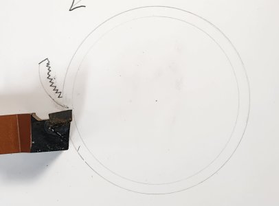
You know, I think the biggest problem in visualizing what's happening is due to the photos. If you had a photo from the end looking toward the chuck, you would think different forces are acting on the cutter. By looking at the Sandvik picture you would think that the majority of the forces are axially. But if you when you look at the quick picture I made, you would think that all the forces are radially.
 

Attachments

  • 20240111_142158.jpg
    20240111_142158.jpg
    92.7 KB · Views: 4
If the face of the bar is bending the edge back, your edge is too knife like and needs to be more close to square.
I don't have any more pictures yet, but to describe the way I grinded the tool. The shape is the same as the tool on the video I watched, but the edge was designed the same way as a knife. With a sharper bevel on the end of the steeper bevel leading up. Like the inserts, is the tool just supposed to have a very small vertical edge around the top of the tool?
 
Chris, would you be able to take pictures of the HSS tool bit you have tried the most? Fairly close up, top, leading side, ( towards chuck side), cutting-ground end (front), as square to the bit as reasionly possible.
Most angles for relief on a HSS bit are small (relatively ), very much like the drill bit. A knife edge will not last long on hard material. The reliefs allow the lathe cutting tool to advance into the work, while not rubbing the work.
If you have no relief on a drill bits cutting edge it wil rub and get hot, (not drilling rubber here). To much relief results in a weak cutting edge, that also suffers a lack of durability.
I hope some of what we are talking about makes sense.
 
That is all familiar on my part from the study I've done on knife engineering. It makes sense that a metal turning tool would need to be rather obtuse instead of acute to resist shaping or bending by force against hard material. I'll take a picture of my tool when I can, and take a look at the angle of the cutting edge on he top of the bevel. I t also makes good sense that the front needs relief in order to cut forward into the face instead of rubbing.
 
Last edited:
We were both typing at the same time it seems. The inserts (carbide) often have a almost blunt, sometimes even slightly rounded edge. A lot of inserts are designed for machines with much more power then you have.
HSS edges are keen? Not razor or even knife sharp. Even a cold chisel or wedge has more angle then general purpose HSS cutting tools for the metal lathe.
Perhaps this might help, draw out a 90 degree angle (rite angle), now draw a 60 degree angle inside that with the points together. Each leg comes in 15 degrees. This will be looking at the end of the bit. This will give you a top relief and a side relief. Put about 15 degrees of angle on the front in both vertical and horizontal. Don't worry about the leading edge, set that with the tool holder/tool post, again about 15 degrees. Set tip on centre.
Hope this makes sense
 
I t also makes good sense that the front needs relief in order to cut forward into the face instead of rubbing.

Not really Chris. It never does cut forward into the face. The work moves downward onto the top of the tool and the chip peels forward toward you.

Yes, relief on the tool is required to prevent rubbing, but not to allow the tool to advance. It is there to stop the work from rubbing as it continues downward past the tool.

If I get some time later tonight, I will try to draw you a few pictures.

My sense of this is that you are a sharp fellow trying too hard to apply your previous knife knowledge to a situation that is very different. You need to stop thinking about cutting like a knife. It's more like pulling your hand or a trowel through mud.
 
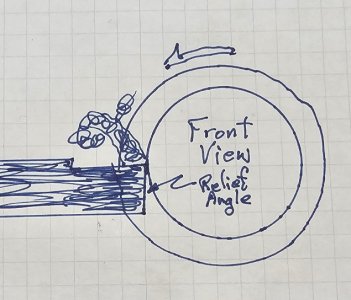
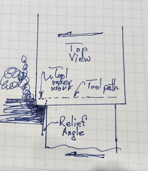
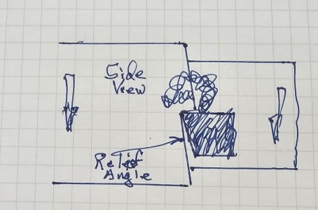
Well, my drawing skills were never great. Here are three drawings - front looking toward the chuck, top looking down at the part, and side view looking at the part from the tool post. The angles are exaggerated but you can see the three required reliefs. The tool is shaded to be dark. And you should be able to see how the metal is being peeled off, not cut off.

Front view looking toward chuck.

20240111_172552.jpg

Top view looking down. Notice the dotted line where the tool is under the part. It was hard to draw the chip without further hiding where the tool is hidden. Just ignore that chip and know that there is one there. Also notice the angle of the tool path across the whole part caused by the feed rate.

20240111_172604.jpg

And this is the side looking from the toolpost in. Notice the feed rate angle on the uncut part. This angle also needs to be considered to make an adequate relief. Small diameter parts with a fast feed rate can be a hidden problem waiting to bite you.

20240111_172600.jpg

Again, all reliefs and angles are exaggerated. One relief is shown in each drawing. Some top relief is usually also included but the tool will work without it. If desired, this top relief is also where you would grind a chip breaker groove.
 
Last edited:
What you see in that video is what I had in mind. It is only showing the progress of the tool after it has pierced the metal. Like I said in the comment above about the only point at which the tool cuts towards the chuck is when it moves forward or progresses into the next layer of material. Without feeding the tool toward the metal or the chuck it doesn't continue to cut after the metal has made a full rotation. It is possible with the proper geometry that a tool could cut forward and upward simultaneously as the stock is turned into the tool which would result in a perfect spiral, but you would have no control over that.
 
Last edited:
Your pictures give a good idea of how much of an angel is needed to cut the metal causing it to curl. I was thinking about the geometry of a sharp knife that would leave long straight strings with the blade following through the metal over one rotation.
 
It is only showing the progress of the tool after it has pierced the metal.

The tool does not Pierce the metal. It just starts gouging its way in to the working depth as the work turns. There is no piercing. Rather it cuts very shallow at first as you advance the tool. Put a different way, if the work is not turning, the tool cannot advance or do anything except press against the work and damage something.

Like I said in the comment above about the only point at which the tool cuts towards the chuck is when it moves forward or progresses into the next layer of material. Without feeding the tool toward the metal or the chuck it doesn't continue to cut after the metal has made a full rotation. that.

There is no progress into the next layer until you make another pass.

You are right, after one rotation, there will be no further progress until or unless you engage the feed (see next discussion). However, letting a lathe rotate without tool advancement is a sure way to damage your cutter. It needs to be cutting something to get rid of heat. If it just turns with no cutting it will overheat from rubbing and be damaged. If you want to just keep it there, you can, but you have to back the tool off so it doesn't rub.

It is possible with the proper geometry that a tool could cut forward and upward simultaneously as the stock is turned into the tool which would result in a perfect spiral, but you would have no control over that.

Actually that spiral is exactly how it is supposed to work and you do have total control of it. You set the feed rate toward the chuck on your lathe feed rate controls, and you dial in the depth of cut on your cross-slide. Except for parting, all cuts should be a spiral. In fact even parting is just a radial spiral whose chips look like clock springs instead of stretched springs.
 
Your pictures give a good idea of how much of an angel is needed to cut the metal causing it to curl. I was thinking about the geometry of a sharp knife that would leave long straight strings with the blade following through the metal over one rotation.

I think it would be best if you put all your knife imagery and knowledge away for a while. It is probably holding you back. It's a bit like an engineer trying to have sex for the first time using formulas. Sometimes you have to throw the books away and just get dirty.
 
Back
Top