• Spring 2024 meetup in Calgary - tentative date Saturday, April 20/2024. Other regions are also discussing meet ups. If you want one in your area get going on organizing it! discussion
  • We are having email/registration problems again. Diagnosis is underway. New users sorry if you are having trouble getting registered. We are exploring different options to get registered. Contact the forum via another member or on facebook if you're stuck. Update -> we think it is fixed. Let us know if not.
  • Spring meet up in Ontario, April 6/2024. NEW LOCATION See Post #31 Discussion NEW LOCATION

Looking for some help with mach 3

jcdammeyer

John
Premium Member
Ok but I don't understand where the pwm signal comes from? it was my understanding the power supply was separate? in my "box" that the G540 is located in the power supply for the G540 is inside, the 0 to 48V supply is pin 11 and 12. according to the pinout 7 is vfd grounf 8 is vfd output and 9 is VFD 10V
Yes. The Gecko manual says don't put more than 12V on the pin 9 VFD 10V. That's the clue that the power for the PWM circuit comes from the VFD (or motor driver). Recall message #4 above where the MACH screens are set for PWM.

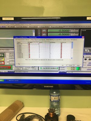
In this case the spindle step pin would be set to pin 14 and no direction output.
1679011212153.png

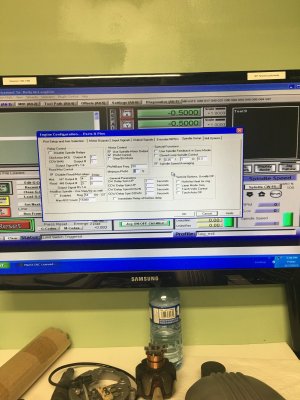
Then under spindle set use Spindle Motor Output and PWM control and 5 kHz
1679011536454.png

Now MACH will create a PWM signal on pin 14 that is 0 when spindle off and fully at the Pin 7 VFD-10V value at full speed.
I believe you can set the VFD pin to 5V and that would now create 0V to 5V output.

A 50% PWM signal (50% ON at 5V or 10V and 50% OFF at 0V results in half the analog voltage out. So either 2.5V if terminal 9 is 5V and 5.0V if terminal 9 is 10V.

So I believe, but I'd have to check further,
1679011800057.png
if this is how your spindle speed is configured then if you do an S2500 M3 the PWM rate from MACH will be 50%, the output voltage for the 10V system will be 5V and theoretically a VFD that uses 0-10V for Motor Speed control will recognize the 5V input value as the command to spin at 2500 RPM.

If you are applying 5V to terminal 9 then theoretically you'd see 2.5V which your motor controller will interpret at 50% of the full speed and also 2500 RPM.

Does this make more sense?
 

Kelly McLaughlin

Well-Known Member
Ok 1 thing at a time, remember you're dealing with an electronic child : )
I ignore the 5V supply and ground in my motor controller but I will use the signal (yellow lead) to receive the output from pin 9 which I will configure somewhere to give 5V instead of 10 (I'll need a ground somewhere). In Ports and pins I will set Spindle step to 14 (the pin on the parallel connector) and leave direction at 0 as it is unused. I'll double check but I think my spindle setup is correct.
So part of my confusion comes from not knowing that PWM is a voltage? Thats what I think now. so in this configuration I don't need the little board or am I off the tracks?
 

jcdammeyer

John
Premium Member
Ok 1 thing at a time, remember you're dealing with an electronic child : )
I ignore the 5V supply and ground in my motor controller but I will use the signal (yellow lead) to receive the output from pin 9 which I will configure somewhere to give 5V instead of 10 (I'll need a ground somewhere). In Ports and pins I will set Spindle step to 14 (the pin on the parallel connector) and leave direction at 0 as it is unused. I'll double check but I think my spindle setup is correct.
So part of my confusion comes from not knowing that PWM is a voltage? Thats what I think now. so in this configuration I don't need the little board or am I off the tracks?
I don't think you need the little board and I think you have to apply power to the VFD Power terminal. I've asked on the MACH support group about that pin.
What you can do is power up your system and measure the voltage between VFD-GND and VFD-10V. Should likely be 0V as will the terminal 8 VFD-OUT.
In other words the 5V or 10V from the VFD terminals (the speed pot connections if connected).
Must run. Chat later?
 

Kelly McLaughlin

Well-Known Member
probably tomorrow I'll go do the tests and record findings. I'm home all day tomorrow except for lunch so I'll get setup in my shop so I'm not running back and forth. Thanks for your help with this. let me know when to be available tomorrow when you have a chance.
 

Kelly McLaughlin

Well-Known Member
Checked Voltage at 8,9 all 0 between 7,8 and 7,9. so the light is slowly coming on, my motor controller should be treated like a vfd. Terminal 7 is the ground / black from my controller. Terminal 8 is my yellow or the output from the VFD terminal 9 is the 5 volt supply from my controller. so mach 3 through my G540 takes the 5 V and varies it and supplies that back to terminal 8 replacing my pot? we'll see if I pass or fail : )
 

Susquatch

Ultra Member
Administrator
Moderator
Premium Member
A few comments from the peanut gallery @Kelly McLaughlin ...

PWM means Pulse Width Modulated. By varying the pulse width you change the voltage the motor thinks it is seeing.

About zero voltage readings. If you measure an AC voltage with a DC meter, the reading will usually be zero. That doesn't mean it is.

Not sure either comment is relevant but thought I should put it out there anyway.
 

jcdammeyer

John
Premium Member
Got an answer back from Steve Spallings who is a bit of an expert in the MACH area and has likely had the G540 apart.

The circuitry works better at 10 or 12 volts, but it will function at 5 volts.

The issue is that the output range is limited to between approximately Gnd plus about 0.3 volts and Supply Voltage minus 0.6 volts. This does not change as you lower the supply voltage so the limitation gets worse percentage wise as the supply voltage is reduced.

If you need better results you could provide an isolated 12 volt supply and then use a resistor divider on the output to scale the range to 0-5 volts.

The circuit also uses an active filter to help smooth out the PWM frequency more than a capacitor alone would smooth it.
And he's right about using the 10V and dividing it down with a resistor to 5V max. However without knowing more about the motor controller circuit or the drive capability of the GECKO G540 it's hard to decide which resistors to use. One could experiment but you did say you weren't electronically oriented so your supply of resistors is probably pretty small.
 

jcdammeyer

John
Premium Member
Checked Voltage at 8,9 all 0 between 7,8 and 7,9. so the light is slowly coming on, my motor controller should be treated like a vfd. Terminal 7 is the ground / black from my controller. Terminal 8 is my yellow or the output from the VFD terminal 9 is the 5 volt supply from my controller. so mach 3 through my G540 takes the 5 V and varies it and supplies that back to terminal 8 replacing my pot? we'll see if I pass or fail : )
If you apply +5V to the Pin9 and the -5V (Gnd) to Pin7 and then measure voltage between the output Pin8 and Pin7 gnd.

In the MACH3 MDI screen enter in S1000 M3. You should see a voltage. What that voltage is will depend on what you max RPM is set to in MACH configuration. The manual should help you figure that out. You can try various RPMs to see how well they match as a percentage of RPM. That's why it's easier to experiment with 10V on the Gecko VFD Voltage pin. 3.75 is 37.5% of your max RPM for example.
 

Kelly McLaughlin

Well-Known Member
Hi John! I'll make those changes today and let you know this evening how I did. The one downfall of the G540 manual is there's no real explanation of how things work. I guess it's written assuming you have an electronics background. I'll be back : )
 

jcdammeyer

John
Premium Member
Hi John! I'll make those changes today and let you know this evening how I did. The one downfall of the G540 manual is there's no real explanation of how things work. I guess it's written assuming you have an electronics background. I'll be back : )
The manual is shit. Excuse the expression. There's no specification on how much current the PWM output can supply at 10V nor whether it's really 0.3V to 9.4V which is more likely. Again most VFDs won't let an AC 3 phase motor go down to less than about 10% so that would be 1.0V and often the 10V is for double the speed so a tiny bit off that is probably also not an issue.

But that's all beside the point.
 

Kelly McLaughlin

Well-Known Member
Hi John! made those changes. No output at pin 8 could I have something configured incorrectly? I made the changes to the step dir as suggested and entered S1000. I reset the over ride and it changed to 100% is there something else I need to do? I will research this afternoon.
 

jcdammeyer

John
Premium Member
Hi John! made those changes. No output at pin 8 could I have something configured incorrectly? I made the changes to the step dir as suggested and entered S1000. I reset the over ride and it changed to 100% is there something else I need to do? I will research this afternoon.
Let me fire up a MACH3 system and take a look. I don't use spindle speed with my router as it's just a small Bosch Colt. But I do run MACH3 and I have a breakout board connected. I'll report back after doggy walk.
 

Kelly McLaughlin

Well-Known Member
when I hit enter the relay fires and the RPM screen begins counting but then returns to 0, in case thats significant. heading for lunch, back about 1:30 my time so no rush : )
 

Kelly McLaughlin

Well-Known Member
Hi John! called Gecko wanted to be sure this was a straight through circuit, they verified that the G540 can use anything from 0 to 10 and should provide an output based on % he did say duty cycle needs to be 100% looking for that setting now.
 

Kelly McLaughlin

Well-Known Member
I believe I have all the settings I know about correct. But..... we've supplied the 5V signal to the G540, the relay is connected properly as it fires when the spindle is activated. what makes the circuit between the 5V source and the reduced voltage pin (8) to adjust the motor controler? Pin 14 on the parallel port is how it is transmitted but I'm not sure I've configured anything to turn it on with the spindle. not sure I'm asking my question well but hopefully you understand what I mean : )
 

jcdammeyer

John
Premium Member
I believe I have all the settings I know about correct. But..... we've supplied the 5V signal to the G540, the relay is connected properly as it fires when the spindle is activated. what makes the circuit between the 5V source and the reduced voltage pin (8) to adjust the motor controler? Pin 14 on the parallel port is how it is transmitted but I'm not sure I've configured anything to turn it on with the spindle. not sure I'm asking my question well but hopefully you understand what I mean : )
CTRL-SHIFT-PrtScn to capture the screen. Then paste it into Paint or some other graphics program and save as a jpg or bmp file. Paste that here so we can see the MACH setup screen for the spindle. Like I did above.
 

Kelly McLaughlin

Well-Known Member
I believe I have all the settings I know about correct. But..... we've supplied the 5V signal to the G540, the relay is connected properly as it fires when the spindle is activated. what makes the circuit between the 5V source and the reduced voltage pin (8) to adjust the motor controler? Pin 14 on the parallel port is how it is transmitted but I'm not sure I've configured anything to turn it on with the spindle. not sure I'm asking my question well but hopefully you understand what I mean : )
 

Kelly McLaughlin

Well-Known Member
Here you go! I took one of anything I thought might help : )
 

Attachments

  • IMG_0472.JPG
    IMG_0472.JPG
    449.1 KB · Views: 2
  • IMG_0473.JPG
    IMG_0473.JPG
    434.4 KB · Views: 2
  • IMG_0474.JPG
    IMG_0474.JPG
    457.9 KB · Views: 2
  • IMG_0475.JPG
    IMG_0475.JPG
    454 KB · Views: 2

jcdammeyer

John
Premium Member
Actually they do help. I disabled my direction relays and then it complained because I didn't have direction set in the spindle on the Motor Outputs screen. I will try it the way you have. My Break Out Board connected to the USB Smooth Stepper has LEDs on PIN14 and PIN16 which I have set as speed and dir. I'm not seeing it come on so I may have to haul out the scope.
Also the 50kHz for your PWM rate may be way too high. Drop it back down to 5kHz. The filter circuit in the G540 may not let that high a frequency pass.
 
Top