• Scam Alert. Members are reminded to NOT send money to buy anything. Don't buy things remote and have it shipped - go get it yourself, pay in person, and take your equipment with you. Scammers have burned people on this forum. Urgency, secrecy, excuses, selling for friend, newish members, FUD, are RED FLAGS. A video conference call is not adequate assurance. Face to face interactions are required. Please report suspicions to the forum admins. Stay Safe - anyone can get scammed.

Looking for some help with mach 3

Hi John! I had it set at 5 until I spoke to the fellow at gecko (it was what your screen shot showed) He told me it should be 50 I watched a video today where the fellow had his at 250, I think the software says from 100 to 500 so I'll set it back to 5 and we'll see what you get from your inquiry. singing off! sorry for the trouble.
 
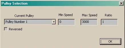
So I have the small BoB properly working for PWM output. Turns out that I had made a mistake in the reverse engineering of the board and had the P1 pin driving the opto-isolator rather than sinking current. That means the P1 Spindle Step pin has to be inverted in the MACH3 setup. Once I did that even just 5kHz was fine for creating the correct 0-10V value for 0 to 3000 RPM. Pulley #1 is configured for max 3000 RPM.

If I send S1500 M3 I then see 5V output. What this means is with a Gecko G540 that outputs 0-10V you can set the pulley speed to twice the max speed of the motor at 10V. Then at 5V out you get the target speed.

eg. Max spindle speed is say 6000 RPM. Set Pulley 1 to 12,000. Now as long as you never select more than 6000 RPM with the S Gcode commands you won't get more than 5V out.

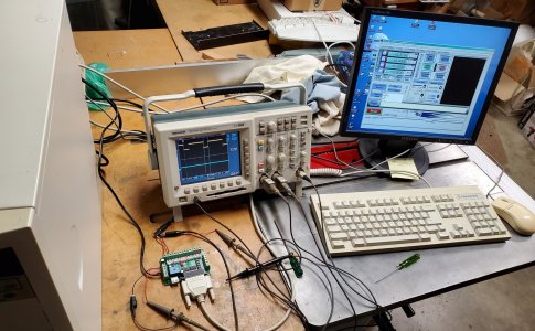
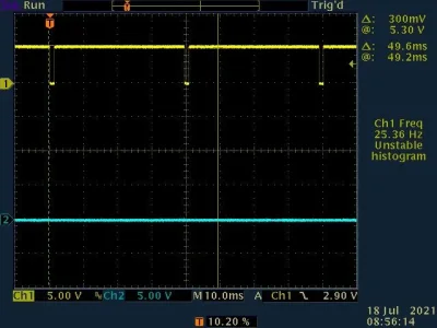
This photo shows the top trace of the scope showing DB25-1 which is the PWM from MACH3 25kHz. Bottom trace shows the DC voltage out from the PWM circuit. Speed is set at 750 RPM with a max speed on pulley 1 of 3000 RPM. So we get a 25% low period duty cycle and about 2.5V on the scope. The PC is 1GHz, 512MB memory WIN-XP and originally ran MACH2 when I was first testing the ELS so it's circa 2006.
BoBTestSetup.jpg
 

Attachments

So I have the small BoB properly working for PWM output. Turns out that I had made a mistake in the reverse engineering of the board and had the P1 pin driving the opto-isolator rather than sinking current.

Could not help but notice.....

Seemed so appropriate!

Also seems as good a time as any to apologize for all the many times I mimicked your humour.

Screenshot_20230318_080623_Chrome.jpg
 
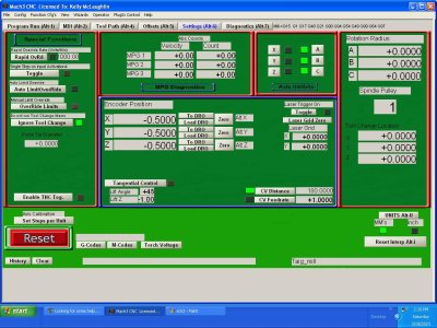
Hi John! I changed to this, I think thats what you meant? still no output. set hz to 5 no joy, I sent the output screen in case there's something I need to configure there? I get the feeling I've missed turning something on or setting a pin correctly.
 

Attachments

  • scn2.JPG
    scn2.JPG
    137 KB · Views: 3
  • Scn1.JPG
    Scn1.JPG
    140.3 KB · Views: 3
My version of MACH complains when I don't have a direction set for the spindle. And of course if I set the dir to pin 17 it complains I'm using the pin twice. So then I went and disabled the output 1 and disabled the direction relays on the spindle setup screen. The DB25-17 on the BoB switches a small relay from the signal called P17_BDIR. When I change from GCode M3 to M4 on the MACH3 MDI screen the relay clicks and I see the LED for it come on.

Therefore I wasn't able to totally duplicate what you have because it won't let me. Try what I did. Set the Spindle DIR to 17. Disable the spindle relays. The set S300 M3 and use a meter to check the Pin 17 output. Then do M4 and check the Pin 17 output. That will tell you that the Motor Control Use Spindle Output is working for the direction side of things. You have to remember to click 'Apply' on that screen too. That caught me a few times when the frequency reverted back to 5 from the 25 that I tried.

Make sure your pulley #1 max speed is set
1679159080876.png

and verify that on the Alt6 Settings screen.
1679159036639.png

It appears to be that number and Max Speed aare used when you do the S3000 G-Code and that creates the 10V. If you do S1500 then it would make 5V. Now if you see closer to 10V at S30 then you have to invert the Step Pulse.
 
One other thing. If you are using a meter to measure things remember that the VFD GND is separate and isolated from the PC GND. So in the drawing below the PC5V and PCGND come in on the little connector on my BoB. The PC5V pushes current through the EL817 out the P1_PWM pin out to the PC which pulls it to PCGND and therefore turns on the Opto.


1679159566508.png


Notice the other side of the OPTO and the PWM output is referenced to GND. That's like the VFG GND on your Gecko. So you can measure the P1 pin (or P17) on the PC side relative to PC GND but you have to put the meter black probe on the VFG_GND pin on the GECKO to measure the VFD voltage. So POS 5 and POS 6 on your Gecko have to be measured relative to POS12.
 
Hi John! had some chores that needed attending but One thing we have to consider is what I'm dealing with is not a VFD it is the three leads from the motor controller for the servo motor. they were run to a magnetic pot, probably the wrong name but you'll understand. so the red and black in that harness is 5v and gnd the yello which is signal needs to use that ground for the controller to work properly. I may be able to attach it to the PC ground with no issues but I'll experiment with that later today. Thanks again.
 
Hi John! had some chores that needed attending but One thing we have to consider is what I'm dealing with is not a VFD it is the three leads from the motor controller for the servo motor. they were run to a magnetic pot, probably the wrong name but you'll understand. so the red and black in that harness is 5v and gnd the yello which is signal needs to use that ground for the controller to work properly. I may be able to attach it to the PC ground with no issues but I'll experiment with that later today. Thanks again.
Yes I understand that. And theoretically just injecting a signal in place of the pot wiper should work. But it also may require some additional resistors. No idea yet.

So first take a step back and don't connect your motor driver. If you have an adjustable power supply set it to 10V and use that for VFD_GND and VFD_10VDC on the GECKO. Next set up MACH as we've discussed and use a meter between VFD_GND and VFD_OUTPUT on the GECKO. If you don't have 10V try the 5V from the motor driver but again don't connect the yellow wire.

What we first want to do is make sure that MACH3 is correctly configured and that the GECKO is behaving.

Again a scope would be handy but you should see the Gecko POS 6 change from S0 to S3000. At least on the PC side POS 6 and meter ground on POS 12 I believe. ie. Get the MACH3 stuff working first.
 
Last edited:
Hi John! I've had the 5v from my motor controller (this is a seperate connector on the box that is 5V + - and the yellow signal) connected all along, the yellow or signal is disconnected, you are correct the g540 ground is isolated from the pc as well as the power supply for the G540. I do not have a variable power supply so I'll have to stick with the 5v just to be sure I turned the spindle on and tried the signal to ground bar and no results.

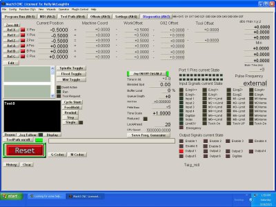
I'm using pin 17 to fire the relay for the spindle and can see it is active in the diagnostic screen. see attached. I have both output 1 and 2 set to port 1 as the spindle direction control is done in my motor controler and output 2 is unused at this time but is intended as an on off for mist or flood coolant etc. if I check disable the relays they cease to work and if I uncheck they begin to work again. So these two outputs are on off in my setup and work perfectly. I've used it that way for several years.

I swapped pin 17 for pin 16 and when I turn on the spindle the relay opens and closes rapidly?
then I swapped pin 16 for pin 14 and on a whim decided to check for ac at terminal 8 and it showed 7.95 volts? tried different spindle commands but no change, then experienced a technical difficulty and lost my power supply : ( It will take a few days to remedy that so I'll be in touch as soon as I'm back up and running. in the mean time let me know what you think of my findings.
 

Attachments

  • scn4.JPG
    scn4.JPG
    158.4 KB · Views: 1
  • scn3.JPG
    scn3.JPG
    156 KB · Views: 1
Hi John! I've had the 5v from my motor controller (this is a seperate connector on the box that is 5V + - and the yellow signal) connected all along, the yellow or signal is disconnected, you are correct the g540 ground is isolated from the pc as well as the power supply for the G540. I do not have a variable power supply so I'll have to stick with the 5v just to be sure I turned the spindle on and tried the signal to ground bar and no results.

I'm using pin 17 to fire the relay for the spindle and can see it is active in the diagnostic screen. see attached. I have both output 1 and 2 set to port 1 as the spindle direction control is done in my motor controler and output 2 is unused at this time but is intended as an on off for mist or flood coolant etc. if I check disable the relays they cease to work and if I uncheck they begin to work again. So these two outputs are on off in my setup and work perfectly. I've used it that way for several years.
I think you may have missed my point. Once you are using the Spindle Control the Motor control step/dir signals are in use. That means you can't have the same direction pin enabled as an output. So yes, the old way has worked but it's not the way you are doing things now. I think that's why my version of MACH bitches at me when I have the spindle Step Pin assigned but nothing assigned to the Dir pin.

And if I assign Pin 17 to the Spindle Dir and I also have it assigned to Output 1 then it complains again because I'm using it twice. So I have to disable the Output 1 as I want Pin 17 as Spindle direction. And then in the Spindle Config screen I also have to disable the Spindle Relays.


I swapped pin 17 for pin 16 and when I turn on the spindle the relay opens and closes rapidly?
then I swapped pin 16 for pin 14 and on a whim decided to check for ac at terminal 8 and it showed 7.95 volts? tried different spindle commands but no change, then experienced a technical difficulty and lost my power supply : ( It will take a few days to remedy that so I'll be in touch as soon as I'm back up and running. in the mean time let me know what you think of my findings.
Testing for AC is erroneous on pin 8 because its a DC output from 0 to 10V (or your VFD supply).

This is why I'm suggesting forget about the motor for the moment. Make sure MACH3 and the GECKO are behaving correctly. If the outputs are set correctly then S0 and S3000 (or whatever your max pulley is set to) will create 0V and 5V (approx) on PO6 of the Gecko. That's the 5V signal applied to their internal PWM 5V to 0-10V DC converter. Like the little external modules you acquired.

In my case the little BoB has that 5V PWM to 0-10V DC converter. I could also pull out the stand alone ones but since I have a scope I don't need to. I'll see if I can get some more screen shots for you.
 
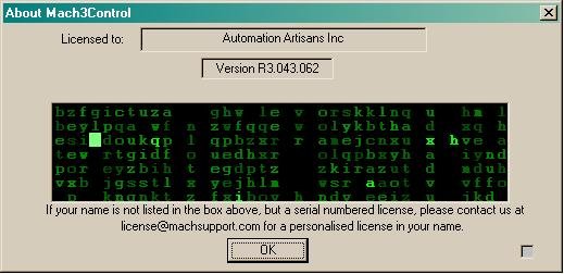
Alright. Went back to the system. Found a 720K 3.5" floppy so I could do some screen saves from the old TEK scope. Let's start here: This is the version I'm running with screen shots from the actual hardware.

Version.JPG


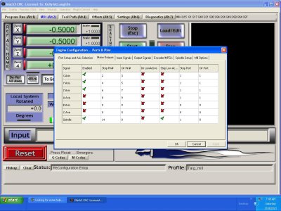
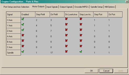
Now let's take a look at the screens. Notice I have Pin 1 set as STEP and Pin 17 set as DIR. On the BoB Pin 1 goes into the PWM circuit to create the 0-10V and pin 17 runs a relay that can be used to switch motor direction. Much like what you have.
PortsPins-Motors.JPG


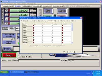
Next let's go to the Outputs screen and make sure nothing is set.
PortsPins-Outputs.JPG


Finally in the Spindle setup screen we have disabled Spindle Relays, Use Spindle Motor Output with PWM control. PWM base frequency is set to 25kHz.
PortsPins-Spindle.JPG


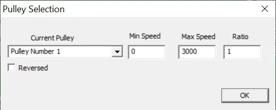
Apply and save and then from the Config menu choose Pulley Selection. I want Pulley # 1 to be the current pulley with a max spindle speed of 3000 RPM and that's the motor RPM since the Ratio for the pulley is 1:1
Pulley.webp


Now let's run it at 100 RPM in the CW direction. The relay on the little board is OFF. The top yellow trace is the PWM signal (active low from 5V to 0V) showing a very small pulse for 100 RPM. The direction signal is the blue one and is low or 0V.
S100_M3.webp


If I type in an M4 on the MDI screen I want to reverse the direction. The relay comes on.
1679185176986.webp

And the direction (blue trace) changes to logic 1 (5V).
S100_M4.webp


Now let's go back to clockwise which is blue trace low and this time 2800 RPM which is almost continuously ON for the PWM (logic low since it's inverted) with just a short time OFF (logic high)
S2800_M3.webp


At this point as long as there is a module connected to the PIN1 with that 5V PWM I can create 0V to 10V which this little BoB does. But I could use an external module too. Or in the case of the Gecko it routes Pin1 through an optical isolator over to the PWM to DC circuit and puts it out on VFD_PWM with the supply for the isolator coming from VFD_GND and VFD_10V.

The scope leads in the above samples are on PCGND and the buffered PC Parallel Port signals.

Maybe this will clear things up?
 
Hi John. Actually just came up from looking at it for the first time since my power supply issues. There is definitely something odd going on. I have 5Vdc on pins 7 and 9 but when I test pin 8 with the meter on DC it shows a mv reading and flashes random numbers .152 etc. if I switch my meter to AC then between pins 7 and 8 I get 8 to 9.5 V AC depending on wether the spindle is on or off. if I shut the power supply off, both voltages disappear so the AC is a result of the DC input somehow. When I called gecko and from everything I've read if you put a voltage in on 7 and 9 the voltage at 8 should be at least the same type so I'll keep digging and call gecko in the morning and see what they say. I'm stumped. I did find online a manual fro Sogineris (spelling) that showed the Mach3 pins settings for a 5V setup like mine and confirmed it must use 50HZ so I've made those settings but until I get the AC DC thing sorted i'm on hold. I appreciate your help but I won't waste any more of your time till I'm confident I have basic things correct.
 
Pretty sure the PWM base frequency is in kHz not Hz but if you are using a smooth stepper then 50kHz shouldn't be a problem as long as your kernel speed is also high enough. I was running a 25kHz kernel speed on the parallel port so getting the 25kHz PWM isn't an issue.

And you didn't say whether you had turned off the Relay Control for Disable Spindle relays and set the port direction bit to that relay bit as shown above in my screen shots.
If those things aren't correct it's hard to know what MACH will do as an input into the Gecko. And without a scope you can't confirm what's going on.
So three things:
1. PWM frequency less than kernel frequency.
2. Disable Spindle Relays
3. Set Spindle Step and Direction pins.
 
Hi John! It took some time but i was able to repair my power supply. I found a diagram in the internet for a Soigeneris controller that was using my exact setup, a pot for speed control that was switched to use mach3. (I didn't have the switch) I was able to make the spindle work with their settings. but was only able to get 1200 rpm as max speed using the pwm setup. I've reinstalled my pot and my system works the way it always did so I've decided to spend the time learning to run mach3 and I'll source a 10V power supply as thats whats intended and reconfigure things at that point to see if I can make it work the way I'd like. Thanks for your help I will likely bother you at some point in the future once I'm more fluent : )
 
Hi John! It took some time but i was able to repair my power supply. I found a diagram in the internet for a Soigeneris controller that was using my exact setup, a pot for speed control that was switched to use mach3. (I didn't have the switch) I was able to make the spindle work with their settings. but was only able to get 1200 rpm as max speed using the pwm setup. I've reinstalled my pot and my system works the way it always did so I've decided to spend the time learning to run mach3 and I'll source a 10V power supply as thats whats intended and reconfigure things at that point to see if I can make it work the way I'd like. Thanks for your help I will likely bother you at some point in the future once I'm more fluent : )
Bother away whenever you want.
 
Back
Top