• Spring 2024 meetup in Calgary - tentative date Saturday, April 20/2024. Other regions are also discussing meet ups. If you want one in your area get going on organizing it! discussion
  • We are having email/registration problems again. Diagnosis is underway. New users sorry if you are having trouble getting registered. We are exploring different options to get registered. Contact the forum via another member or on facebook if you're stuck. Update -> we think it is fixed. Let us know if not.
  • Spring meet up in Ontario, April 6/2024. NEW LOCATION See Post #31 Discussion NEW LOCATION

Looking for some help with mach 3

Kelly McLaughlin

Well-Known Member
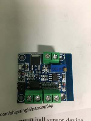
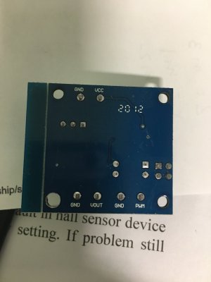
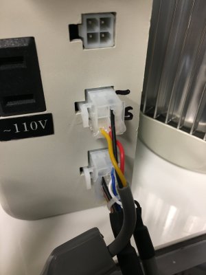
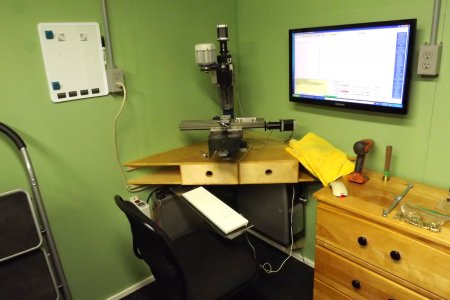
Hi Folks. Not sure if this is the right place for this. I'm trying to run the spindle on my taig CNC with the pwm function of Mach 3. I converted the spindle to a 3/4 HP industrial sewing machine motor several years ago using it's controller and wired in a pot to vary the speed. I've been using a relay to control the spindle on off for some time now and this has worked well with the software I was using. I'm now forced into using Mach 3 (which I've owned for some time) so I'm thinking if I'm learning I might as well make it work for me. I'm trying to make the PWM adjust the 5V signal that was the pot to vary the speed of the spindle. I have a small board that I think should work but I'm struggling to configure things as the tutorials I've found are for a VFD it seems. Any direction would be appreciated : )
 

jcdammeyer

John
Premium Member
Your pot will have one end connected to 5V the other side to ground. The issue though might be that the ground is floating relative to some other voltage or ground so it's important to be very careful. Maybe measure the ground pin to Earth, frame with both AC and DC settings.

Even then it's probably a good idea to optically isolate the PWM signal from the pot. I have a HomannDesigns DC-06 (no longer sold and I've emailed to ask why). It provides an isolated 0-5V signal and is meant to interface to MACH3.

I've attached the user manual for you to look at.
 

Attachments

  • DC-06V3R2.pdf
    557.4 KB · Views: 2

Kelly McLaughlin

Well-Known Member
Hi John! Thanks for your reply. I'm Sorry I think I had too much info in the post. I'm not using the pot, I have this board that is opto isolated that I think should work but I'm not positive, I have 0 knowledge in this area and am a rank beginner with Mach 3. The connector on top in pic 3 is the 5v harness for speed control, I ran it to a pot Black and red are power and ground and yellow is signal. My thinking is ti use the black red through the board and use pwm to vary the voltage to yellow which is how the pot was wired. meanwhile I'll look at your docs.
 

Attachments

  • IMG_0465.JPG
    IMG_0465.JPG
    289.7 KB · Views: 1
  • IMG_0466.JPG
    IMG_0466.JPG
    214.7 KB · Views: 1
  • IMG_0467.JPG
    IMG_0467.JPG
    246.2 KB · Views: 1

jcdammeyer

John
Premium Member
That looks exactly like the two I have. It's in the yellow box on top of the interface to the AC Servo Drive. Top left corner of the yellow box has a small black cable running over to the middule of the drive for the PWM input to the drive.
I'm running this with a Raspberry Pi to a MESA board to a break out board to my interface board.
Pi4_7i92_BoB_PWM_Bergerda.jpg

The AC servo was designed for 0 - 10V in. If your drive uses 0-5V then the 10V which would be 100% PWM is too high. I'd have to look at my module in detail to see if it can be restricted to max 5V output. Or you'll have to create a voltage divider to ensure it doesn't go too high.
PWM from MACH3 is easy.

1678753050103.png

1678753164685.png
 

Kelly McLaughlin

Well-Known Member
OK I'll study this and make the changes to software, My thinking was if I use a 5V input I'd be safe? or does it need 10V to function properly?
 

Kelly McLaughlin

Well-Known Member
Got some coming asap. I couldn't find those at the time, I have two 4.5 to 10 and 12 to 24 jumpered, yours if you can use them, send me an address I'll drop them in the mail : ) live and learn!
 

jcdammeyer

John
Premium Member
Got some coming asap. I couldn't find those at the time, I have two 4.5 to 10 and 12 to 24 jumpered, yours if you can use them, send me an address I'll drop them in the mail : ) live and learn!
I have two of the Chinese 0-10V types plus the DC-06 from HomannDesigns. Was going to give you that one but I can't find the data sheet which is why I contacted Peter. Might well be it can do 0-5V. I remember there were issues with it with respect to using it with my ELS. I think it required a faster PWM than I could produce. Not sure anymore.

I switched my spindle drive on the mill over to step/dir instead of PWM. I can now run it 1 RPM if I want and can even position it relative to the index pulse from the encoder. I do need one of my 0-10V units for the GS2 running the lathe. As yet I've not done the code to create the PWM.
 

Kelly McLaughlin

Well-Known Member
You're welcome to these, they will be chinese for sure but they will not do anything for me. I ordered 3 of the 5v ones (I like to have spares) I'm using a dc brushless 1HP will my setting be the same as yours? I'll check in tomorrow gotta sign off.
 

jcdammeyer

John
Premium Member
You're welcome to these, they will be chinese for sure but they will not do anything for me. I ordered 3 of the 5v ones (I like to have spares) I'm using a dc brushless 1HP will my setting be the same as yours? I'll check in tomorrow gotta sign off.
Save them for someone else on the list. As I said, I have two plus the DC-06 which is likely 2 more than I actually need. Add that I now have these Chinese Break Out Boards that also create 0-10V on pin 1 for spindle speed control. That one I reverse engineered and drew a schematic. Never did bother with the 0-10V modules.
 

Kelly McLaughlin

Well-Known Member
Thought I'd best make sure you had all the information. I'm using a G540 motion controller (it was supplied with my mill) but I replaced the 110V motor with an industrial sewing machine motor and I'm using the controller from that to run its servo motor. I'm getting the pwm signal from the VFD out on the G540 terminals 8 & 9 I think. at least this is what I think, like I said I'm no electronics tech I just keep at it till I come up with a solution...... or not : ) so the red / black / Yellow that went to the speed control for sewing are red, 5V black,gnd and yellow signal. I had wired them to a pot and it worked for years. Now I'm thinking the black / red go to the 5v in the +- from G540 8/9 are pwm + - and the yellow is again signal, it needs a - and I'm not sure which to use, I think it should be the black from the black red pair as thats what it used originally? this is the setup, I've changed it around since the photo but components are the same. I just want to be sure i didn't leave out something important : )
 

Attachments

  • IMG_0467.JPG
    IMG_0467.JPG
    246.2 KB · Views: 3
  • DSCF0984.JPG
    DSCF0984.JPG
    299.1 KB · Views: 3

jcdammeyer

John
Premium Member
Thought I'd best make sure you had all the information. I'm using a G540 motion controller (it was supplied with my mill) but I replaced the 110V motor with an industrial sewing machine motor and I'm using the controller from that to run its servo motor. I'm getting the pwm signal from the VFD out on the G540 terminals 8 & 9 I think. at least this is what I think, like I said I'm no electronics tech I just keep at it till I come up with a solution...... or not : ) so the red / black / Yellow that went to the speed control for sewing are red, 5V black,gnd and yellow signal. I had wired them to a pot and it worked for years. Now I'm thinking the black / red go to the 5v in the +- from G540 8/9 are pwm + - and the yellow is again signal, it needs a - and I'm not sure which to use, I think it should be the black from the black red pair as thats what it used originally? this is the setup, I've changed it around since the photo but components are the same. I just want to be sure i didn't leave out something important : )

I found this when I searched for G540 motion control. Unfortunately it doesn't say how the 0-10V is produced. Do you have a diagram for your existing system?
MAIN-G540-Wiring-Diagram.png
 

Kelly McLaughlin

Well-Known Member
I'm sorry I don't have a diagram, but this is very close. I'm switching the 5V from my motor controller with the relay as shown and using pin 7 and 8 which are pwm ground and pwm output respectively which I think are the pwm signal? sorry for my lack of knowledge.
Normally the 0 to 10 volts would come from another power supply from what I could figure out.
So according to what I think and I could easily be wrong. the 5V for the small board that is in transit is the 5v from my controller. Terminal 7 and 8 are the PWM terminals and the yellow and a ground yet to be determined are the out...... I hope : ) remember I'm not using a vfd.
 

jcdammeyer

John
Premium Member
I'm sorry I don't have a diagram, but this is very close. I'm switching the 5V from my motor controller with the relay as shown and using pin 7 and 8 which are pwm ground and pwm output respectively which I think are the pwm signal? sorry for my lack of knowledge.
Normally the 0 to 10 volts would come from another power supply from what I could figure out.
So according to what I think and I could easily be wrong. the 5V for the small board that is in transit is the 5v from my controller. Terminal 7 and 8 are the PWM terminals and the yellow and a ground yet to be determined are the out...... I hope : ) remember I'm not using a vfd.
Pin 7 and 8 of what?
 

jcdammeyer

John
Premium Member
Pin 7 and 8 of the G540 the diagram shows them going to the VFD that I don't have. : )
You haven't said which version but assuming Rev 4....
Page 5 lists the pin descriptions. They state that the VFD 10VDC should not exceed 12V. That implies it's an input and the supply to the 0-10V output. So it might well be possible that you could apply 5V to it and then get 0-5V. All depends on the Gecko Internal circuitry.
I would contact Gecko and ask if you applied 5V to the 10V pin instead of 10V would you get 0-5V out?
 

jcdammeyer

John
Premium Member
I don't think so. I think they have a small circuit inside that takes the output from Pin 14 on the DB-25 (which is what you would set to Spindle PWM pin on MACH. Since the little side var on that page says optically isolated output it could be as simple as an opto-isolator with a filter capacitor on the output. In which case using 5V instead of 10V into VFD-10V POS9 and VFD-GND POS7 would give out roughly 0V to 5V on VFD-Output.

I'll sketch a circuit for how I think it works later today and post it. They might also have an op-amp powered by the VFD-10V in but I doubt it. Still best to ask Gecko what that circuit looks like.
 

Kelly McLaughlin

Well-Known Member
Ok but I don't understand where the pwm signal comes from? it was my understanding the power supply was separate? in my "box" that the G540 is located in the power supply for the G540 is inside, the 0 to 48V supply is pin 11 and 12. according to the pinout 7 is vfd grounf 8 is vfd output and 9 is VFD 10V
 

Attachments

  • Screen Shot 2023-03-16 at 5.48.07 PM.png
    Screen Shot 2023-03-16 at 5.48.07 PM.png
    209.7 KB · Views: 0
Top