@Susquatch It is my understanding that you need some kind of disconnect after the plug. a 3HP rated switch would do the trick, and be fully code compliant.Thanks Darren, it's not really about what works. That's the easy part.
-
Scam Alert. Members are reminded to NOT send money to buy anything. Don't buy things remote and have it shipped - go get it yourself, pay in person, and take your equipment with you. Scammers have burned people on this forum. Urgency, secrecy, excuses, selling for friend, newish members, FUD, are RED FLAGS. A video conference call is not adequate assurance. Face to face interactions are required. Please report suspicions to the forum admins. Stay Safe - anyone can get scammed.
-
Several Regions have held meetups already, but others are being planned or are evaluating the interest. The Calgary Area Meetup is set for Saturday July 12th at 10am. The signup thread is here! Arbutus has also explored interest in a Fraser Valley meetup but it seems members either missed his thread or had other plans. Let him know if you are interested in a meetup later in the year by posting here! Slowpoke is trying to pull together an Ottawa area meetup later this summer. No date has been selected yet, so let him know if you are interested here! We are not aware of any other meetups being planned this year. If you are interested in doing something in your area, let everyone know and make it happen! Meetups are a great way to make new machining friends and get hands on help in your area. Don’t be shy, sign up and come, or plan your own meetup!
You are using an out of date browser. It may not display this or other websites correctly.
You should upgrade or use an alternative browser.
You should upgrade or use an alternative browser.
Lathe VFD?
- Thread starter Susquatch
- Start date
I love doing research. Teco
Resources from TECO Europe
The latest Case Studies, Product Manuals and Brochures from TECO Europe.
www.teco-group.eu
@Susquatch It is my understanding that you need some kind of disconnect after the plug. a 3HP rated switch would do the trick, and be fully code compliant.
Just to make sure we are on the same page....
220V Single phase outlet on Wall.
Single phase lathe wiring plugged into it.
Then a 3HP disconnect either at the plug or on the lathe.
From there to the fuses, and on to the VFD.
A thumbs up will do... LOL!
slow-poke
Ultra Member
Fuses sound like a good idea, but are they required by code?Just to make sure we are on the same page....
220V Single phase outlet on Wall.
Single phase lathe wiring plugged into it.
Then a 3HP disconnect either at the plug or on the lathe.
From there to the fuses, and on to the VFD.
A thumbs up will do... LOL!
Seem redundant, that's what the breaker is for?
Fuses sound like a good idea, but are they required by code?
Seem redundant, that's what the breaker is for?
I agree totally. Just me doing something easy that is bullet proof. Can't help myself. 😵😱
Tom O
Ultra Member
I just came across this and thought someone might be interested.
I don't know if this will help. Here's the inside of my lathe control box. I have 220VAC single phase in. Output from VFD is 3 phase to the 1HP lathe motor. Schematic attached too.
I'll prolly have the buss bars, and the VFD but no relays or transformers.
I don't have a coolant pump or an ELS nor do I want them. Under normal circumstances, I'd love to run my lamp the way your is done, but I have learned to totally completely HATE the factory 24V lamp. It burns out if I burp.
So I want to replace it with a 120 or better yet 240V AC LED lamp. Maybe two 120s in series so they can be run off of the 240 input. That is project 42k.
I found a Grizzly schematic for a 240 3phase lathe that I used to get going a month or so ago, but quickly realized I was better off starting from scratch.
I am currently busy roughing out my constraints and operational requirements. Then I'll do a rough schematic, and then start sourcing parts - which will dictate some changes. The wiring itself should be relatively easy after that.
Thanks ever so much for thinking about me and reaching out to help.
I just came across this and thought someone might be interested.
It was only a matter of time. This little gem has some interesting features. Not the least of which is Ethernet support.
Basically, it converts single phase 120 to 3phase 240 but it is limited to 1HP motors.
After much painful thought, I've decided to throw in the towel on front mounting the VFD. I'll temporarily mount it on the front while I set it up and then move it to the back outside of the control box where it's hard to get at. There just isn't a place up front where I can put it permanently and I'm not buying another VFD just for the removable control keypad. I'll add a simple swarf shield out back to keep it from ingesting swarf, accept having to crawl behind my lathe to re-program the VFD when I need to, and get on with this project.
I'm reminded of what a CEO of my previous employer said to me once. "There comes a time in every project when it is time to shoot all the engineers and get on with building the product." He was right, but I think a little too aggressive and we paid dearly for that at times.
Anyway, I've procrastinated a decision on this project for way too long and I need to get on with the VFD 3phase motor conversion.
Oooh...like the Cone of Silence in Get Smart!! I love that idea!Could you mount it above ( Ceiling )so it can swing down or slide down on drawer sliders?
Could you mount it above ( Ceiling )so it can swing down or slide down on drawer sliders?
Oooh...like the Cone of Silence in Get Smart!! I love that idea!
I like it too. But my ceiling is 20 ft high......
You guys are gunna mess me all up. I've accepted defeat and am ready to move on and you are trying to make me fight some more. I need to get that lathe purring like a hot cat before I die!
Attachments
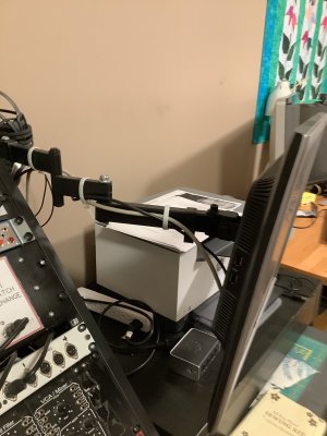
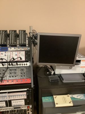
A suggestion - a nice solid monitor arm. They show up on craigslist, Marketplace, etc. for next to nothing, will support 10 to 15 kg, and provide a solid swing away mounting.
That's worth considering!
Project is back on hold while I assess that idea.
I had planned to put the DRO on a swing arm, so why not the VFD too?
I'll have to look at the electrical code again though. Something tells me that this might be outside the envelope.....
Ironman
Ultra Member
Once you get it done, and are loving it, you may consider a remote on/off and speed control pot mounted someplace handy.After much painful thought, I've decided to throw in the towel on front mounting the VFD. I'll temporarily mount it on the front while I set it up and then move it to the back outside of the control box where it's hard to get at. There just isn't a place up front where I can put it permanently and I'm not buying another VFD just for the removable control keypad. I'll add a simple swarf shield out back to keep it from ingesting swarf, accept having to crawl behind my lathe to re-program the VFD when I need to, and get on with this project.
I'm reminded of what a CEO of my previous employer said to me once. "There comes a time in every project when it is time to shoot all the engineers and get on with building the product." He was right, but I think a little too aggressive and we paid dearly for that at times.
Anyway, I've procrastinated a decision on this project for way too long and I need to get on with the VFD 3phase motor conversion.
It really is easy to do. The electric braking is a great adjustment to make in the initial setup too.
a nice solid monitor arm.
I'll have to look at the electrical code again though. Something tells me that this might be outside the envelope.....
After your disconnect on the machine, the CEC no longer applies - from a code compliance point of view. After all, you have modified the wiring which makes it no longer CSA approved anyway.
However, if you do this, then use a flexible steel conduit, and STRANDED of the appropriate gauge in the wires to/from the box that can move.
Once you get it done, and are loving it, you may consider a remote on/off and speed control pot mounted someplace handy.
It really is easy to do. The electric braking is a great adjustment to make in the initial setup too.
That was always the plan.
It's things like fine tuning braking, motor parameters, and frequency, etc that I am trying to make convenient. These are things that are programmed into the VFD. ALL the other stuff will be hard wired to a control panel facing the operator on the headstock.
My bitch was (and still is) convenient comfortable access to the VFD itself for programming. If only my TECO had a removable control panel. It doesn't. That means crawling around in behind my lathe. Not easy at my age. 15 years ago as a young agile boy of 62, it would have been a piece of cake.
Don't you think that's well worth the cost, considering how much time you've spent trying to find other less than perfect alternatives. 😳So I tried to buy a remote control for it....
EMotors wants over $200 for it. I can buy a whole VFD for that!
After your disconnect on the machine, the CEC no longer applies - from a code compliance point of view. After all, you have modified the wiring which makes it no longer CSA approved anyway.
However, if you do this, then use a flexible steel conduit, and STRANDED of the appropriate gauge in the wires to/from the box that can move.
Thanks. I expect that you are correct in all respects.
I was back there earlier this afternoon. I'm not doing the arm thing. Stranded wire for flexibility is the least of the issues. Instead I'm going to mount it on a combined cover bracket on the left side of the existing electrical control box. That allows for a short wire bundle that runs into the box for access to controls, and a very short direct drop to the 3-ph motor.
It looks great facing to the left, but I can't get far enough away from it to read it even with readers on! So it has to face the back wall where there is another foot of space and perhaps even room for a stool. I'll have to see what I have for 6" angle aluminium but buying a piece isn't unreasonable.
It's also possible that I could mount it on the gear box hat I have planned to accommodate the DRO. I'm, going to rough something together out of plywood later this coming week to see if I can kill two birds with the same stone.