• Scam Alert. Members are reminded to NOT send money to buy anything. Don't buy things remote and have it shipped - go get it yourself, pay in person, and take your equipment with you. Scammers have burned people on this forum. Urgency, secrecy, excuses, selling for friend, newish members, FUD, are RED FLAGS. A video conference call is not adequate assurance. Face to face interactions are required. Please report suspicions to the forum admins. Stay Safe - anyone can get scammed.

JCDammeyer's 42 projects

I'd like to have a look at it to see if I could make one.
There's some pretty precise machining required in order to use the tool bit stick-out to also set the tool height. Tool holder is brought up against turned surface until 15/64" drill bit shank is held. Then backed out just enough to let drill bit move. Insert cutting tool and push against surface and then tighten set screws.

Stick-out is now set and so is tool tip height dead on centre. It really does work.

The trick also is in how the tool bit is sharpened.

It's not the best tool bit for turning up to a centre unless maybe it's one of those with a long tip. But still I just turned some aluminum and it came out quite nice. Not as smooth as a carbide insert meant for aluminum but then it doesn't have a really rounded tip either.

You are welcome to come and see it work.
 
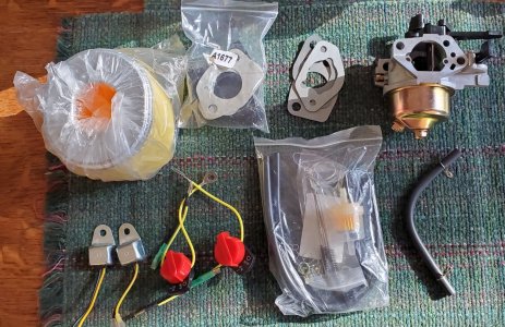
My replacement carburettor for the pressure washer arrived today. In a box was a pink plastic bag `shrink wrapped around another box and the bag with the hoses and clamps and filter. Inside the box was the carb and yet a second ignition switch and second low oil sensor relay.

All for $23.95 and 2 day delivery. I couldn't find anything locally and even just a gasket set without the carb and air filter was $18 and almost 2 week delivery.

CarburatorReplacement.jpg
 
Last edited:
I think I'm 5/5 or maybe 6/6 for replacement carbs now. Not even worth trying to rebuild ones, or find kits for them unless they're in really good shape, or something hard to get a replacement for.
 
Interesting. I looked at various tangential tool holders when I bought mine, but I never looked at the Wimberley in great detail. It’s very different from my Eccentric Engineering version. The EE bit is held vertically, not horizontally like the Wimberley. I might have to make one and try it out.
 
Interesting. I looked at various tangential tool holders when I bought mine, but I never looked at the Wimberley in great detail. It’s very different from my Eccentric Engineering version. The EE bit is held vertically, not horizontally like the Wimberley. I might have to make one and try it out.
I believe the advantage of the diamond tool holder is that it's only one sharpening operation.
The Wimberley requires careful setup of the grinder to get the angles correct but it's sharpened in the tool holder. I have a Lee Valley Tools grinding platform attachment. Like this set but without the plastic thingy.
I have a metal plate that also slides in that groove. I had the lines for guiding tool holder. I think I'll start over and mill a tiny line for each angle. And I've misplaced my 98 degree gauge.
But they are right in that it isn't the tool for everything.
 
Continuing on…..
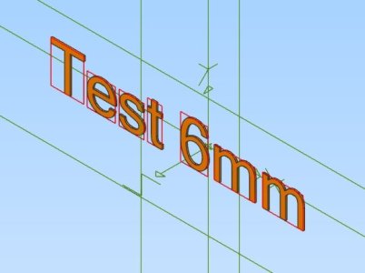
Anyway. Worked it out. New print done. Letters are 0.6mm thick done in three layers. That was another challenge. Getting the black to print first. Following directions on the web on how to do it didn't work all the time. A lot of mucking around.

View attachment 79954
Getting proper instructions for a good quality text print, seems to be a common theme.

Can you please post instructions for what works.
 
Getting proper instructions for a good quality text print, seems to be a common theme.

Can you please post instructions for what works.
1. Text size should match extruder size as in if it's a 0.4mm extruder then no piece of a text letter should be narrower than 0.4mm. Choosing sanserif and bold helps that.
2. Place text onto a surface as a single sketch. No other holes or bumps etc.
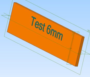
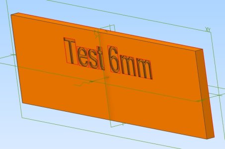
3. Extrude cut that to a depth of 0.6mm and save_as this as a distinct part like the example TestPartBody.jpg.
4. Now remove the extrude cut operation on the text sketch and do an extrude boss in the same direction as the cut was done. Make this object a different colour so it looks like TestPart.jpg if you want to see it.
5. Suppress the body that this text was printed on. If the text vanishes you might have to have put the text on a plane that is even with this body. The part drawing now looks like TestPartText.jpg. Save this as a distinct part.
6. Create an assembly which includes the two parts just saved. As they were both referenced to the same axis they sit on top of each other and again looks like TestPart.jpg. Save this and then export it as a STEP file. Not an STL.
7. In Bambu Labs import the STEP file. Flip the part 180 degrees so the text side is down on the build plate and select look at objects as shown in TestPartPrinting..jpg.
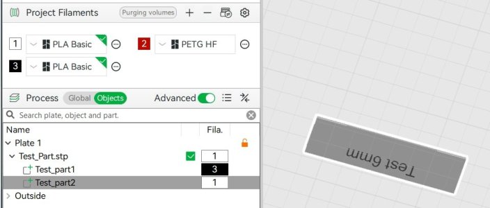
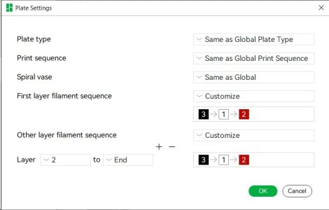
8. By default both parts of the stp file assembly will be the same filament. Chose which filament you wish the text to be and then set the filament order as in Test_Part_Plate.jpg.
9. Start the print.

It should now print the text in say black. Then change filament and print the white. Then change back to black for the next layer and print text. Then white again. Finally the third layer black and white. From then on only white.

If the white is printed first what happens is the filament bleeds into the text areas and the letters are thinner or even covered in white with very little black showing.

Hope that helps.

 

Attachments

  • TestPart.jpg
    TestPart.jpg
    54 KB · Views: 0
  • TestPartBody.jpg
    TestPartBody.jpg
    56.6 KB · Views: 0
  • TestPartPrinting.jpg
    TestPartPrinting.jpg
    52.6 KB · Views: 0
  • TestPartText.jpg
    TestPartText.jpg
    29.3 KB · Views: 0
  • Test_Part_Plate.jpg
    Test_Part_Plate.jpg
    44.5 KB · Views: 0
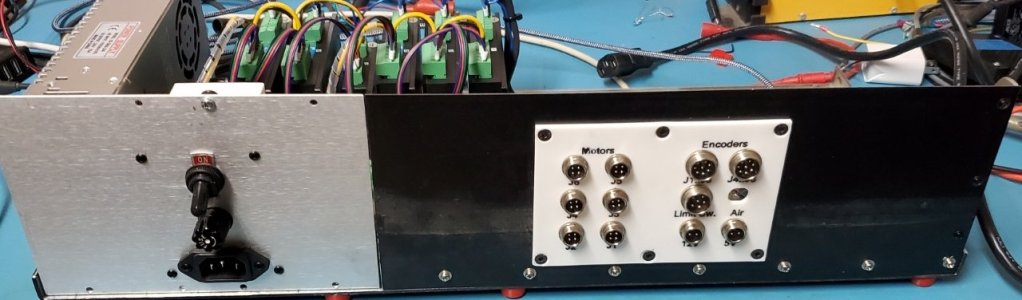
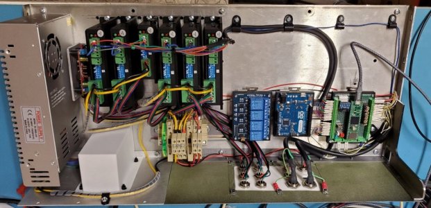
Pretty well all the wiring in the AR3 Robot Arm control box is done. Looking at photos it appears I've been at this project for over 3 years. Mind you there have been a few setbacks so I guess I should be easy on myself. Especially since I have trouble finishing projects.

Here are the photos of the control box. Very tedious crimping tiny connectors onto wires. Soldering to the back of connectors. Old age and being more shaky.

Really upset to find that PLA-CF (carbon fibre) possibly has asbestos type issues. It's still the nicest stuff I've printed. Surface finish is sweet. It's strong. It taps well down to 3mm in 2.5mm printed holes. The only odd thing is with horizontal holes and support the holes aren't really round.

So back to PET-G and ultimately aluminum.

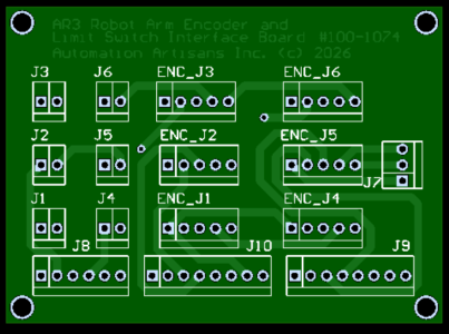
Now for the arm itself I did use point to point wiring but after I was done realized I wanted a 5 pin rather than 4 pin connector for the encoders. Easier to go to PCBWay and order 5 boards for a total with shipping of $15. They should be here in about a week or so.

This goes into the base of the arm. The limit switches and encoders plug into the connectors and then the J8..J10 go out through the aviation connectors to the control box.

That's it for now...
 

Attachments

  • ControlBox-Back-1.jpg
    ControlBox-Back-1.jpg
    93 KB · Views: 4
  • ControlBox-Inside-1s.jpg
    ControlBox-Inside-1s.jpg
    190.8 KB · Views: 4
  • 1775636393421.png
    1775636393421.png
    136.7 KB · Views: 4
That's pretty impressive John. Congrats!
Thanks. Because I started this project over 3 years ago and it morphed from an AR3 to an AR4 with different parts and software I've had to do a lot of fly by the seat of my pants to make it somewhat current.

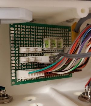
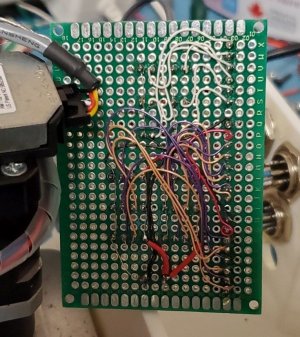
And point to point wiring on a proto board. It had mistakes. Even forgot one wire. Inside the robot case I made my own interface board so that I would haven't glob and solder all sorts of wires and never be able to service it. So now it has connectors but even there I decided later I wanted 5 pin connectors so I've created a PC board that should arrive in a week or two.

RobotBaseInterfaceTop.jpg

RobotBaseInterfaceBottom.jpg
 
Back
Top