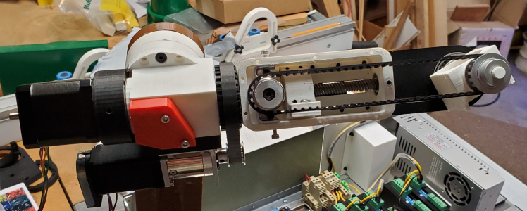
Before I start wiring things I need to replace the 3D printed J2_Arm with one made out of aluminum. The 3D one flexes way too much. The problem is my mill is too small so this is my solution.
Notice I put three 6.35mm holes down the middle spaced 110mm apart. The backing board will get the two left holes and registration pins inserted.
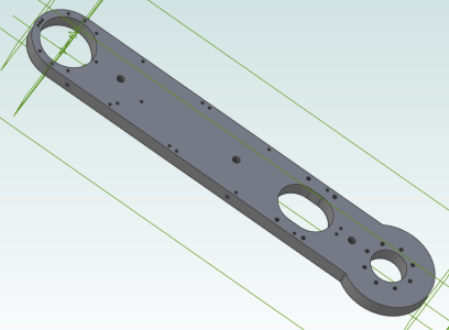
Here's the approach. I cut the part in half but the three registration holes are set up so the middle one is on both pieces. The X=Y=Z=0 position is the centre of that hole. That zero position is the machine X=8.5" and Y=4.0" position and now there's enough space to mill around the left edge. And of coarse the middle hole along with all the little ones.
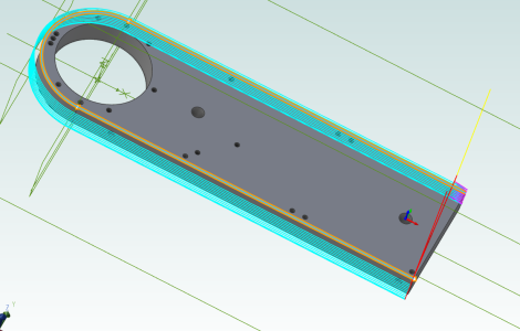
The same part but now with the left side removed. The raw material is lifted up and moved left so what was right hand hole in the original now becomes the X=Y=0 position. Shown by the little coloured arrows.
In effect, moving it 110mm to the left means now the mill can reach the far right side of the part and mill the profile plus the cutouts and drill the holes.
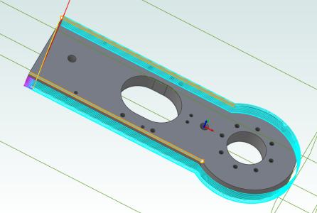
I have a 10mm 3 flute milling cutter meant for aluminum. First set of conventional milling passes around leave 0.5mm and then there is a separate full depth climb milling pass to clean it up.
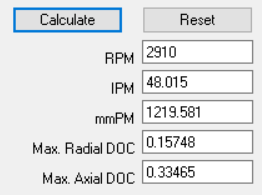
Machinist toolbox says 2910 RPM and 48 IPM. I think doing a 0.1" depth of cut and running about 24 IPM will be more reasonable for my machine. I'll try it on a scrap piece first.
It will take me a few days to get up the courage but I did do some dry runs without the spindle turning or a tool loaded and it all looks good as far as the milling passes.