• Scam Alert. Members are reminded to NOT send money to buy anything. Don't buy things remote and have it shipped - go get it yourself, pay in person, and take your equipment with you. Scammers have burned people on this forum. Urgency, secrecy, excuses, selling for friend, newish members, FUD, are RED FLAGS. A video conference call is not adequate assurance. Face to face interactions are required. Please report suspicions to the forum admins. Stay Safe - anyone can get scammed.

JCDammeyer's 42 projects

Now I remember why I bought linear rails and bearings for the JGRO CNC router. I was carving a bit of oak and totally trashed it. Although the CAM drawing showed a 2.5mm depth of cut it wasn't until I saw the router plunge down 0.357" (9mm) I had to hit the ESTOP.
Nothing strange. The next G-Code was for the correct depth so I ran it again. Waited until it finished that level and stopped it. A bit of measuring showed a difference of more than 0.035" from one end to the other (almost 0.9mm).

WTF? Is my finding the top surface as zero that far off?

Well a bit of investigation now using my newly acquired milling machine CNC knowledge and between Z axis backlash and sag on the y axis rails I now remember why I bought the linear bearings.

I'm amazed I didn't bend or break the router bit with the unexpected motion. sigh...
 
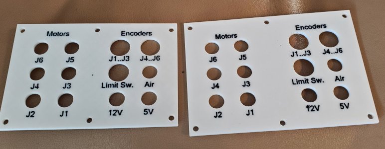
Continuing on with the AR3 Robot Arm the control cabinet back panel is now complete. The first one was a bit small for mounting onto a metal back plate so I made another. Lots of problems. Suddenly after enlarging the panel and rearranging the holes a bit the text would no longer move. Seems I deleted some sort of invisible thing.
Anyway. Worked it out. New print done. Letters are 0.6mm thick done in three layers. That was another challenge. Getting the black to print first. Following directions on the web on how to do it didn't work all the time. A lot of mucking around.

BackPanel.jpg
 
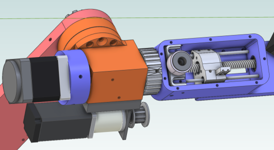
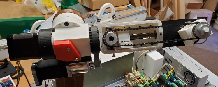
Didn't want to hijack @Golem Pens thread so I'll continue on with that 3D print and non-round hole. A piece of 1" aluminum tube fits in it and is held fast with set screws. The pulley is turned by the small motor which rotates the box.

1774304051961.png

I'm finding the box as printed in PLA is too soft to hold the screws well. Especially the belt tension fixture. 1774304487032.png

The question I have is about creating the two holes in the ends. They have to be symmetrical (as in line) with each other.

If I touch off the same two sides on each end theoretically then drilling and boring to the correct dimension should be adequate.

An alternative method is a long boring bar between centres on the lathe and the part mounted on the carriage at the right height. Then adjust the cutter to cut the correct dimension for each end. But that seems like a lot of work.

Any alternative ideas?
 

Attachments

Before I start wiring things I need to replace the 3D printed J2_Arm with one made out of aluminum. The 3D one flexes way too much. The problem is my mill is too small so this is my solution.
Notice I put three 6.35mm holes down the middle spaced 110mm apart. The backing board will get the two left holes and registration pins inserted.
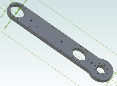
1774403981588.png

Here's the approach. I cut the part in half but the three registration holes are set up so the middle one is on both pieces. The X=Y=Z=0 position is the centre of that hole. That zero position is the machine X=8.5" and Y=4.0" position and now there's enough space to mill around the left edge. And of coarse the middle hole along with all the little ones.
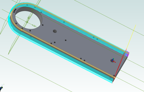
1774404510692.png

The same part but now with the left side removed. The raw material is lifted up and moved left so what was right hand hole in the original now becomes the X=Y=0 position. Shown by the little coloured arrows.

In effect, moving it 110mm to the left means now the mill can reach the far right side of the part and mill the profile plus the cutouts and drill the holes.
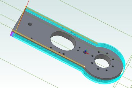
1774404814712.png
I have a 10mm 3 flute milling cutter meant for aluminum. First set of conventional milling passes around leave 0.5mm and then there is a separate full depth climb milling pass to clean it up.

Machinist toolbox says 2910 RPM and 48 IPM. I think doing a 0.1" depth of cut and running about 24 IPM will be more reasonable for my machine. I'll try it on a scrap piece first.
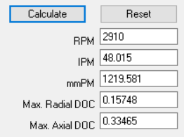
1774405172233.png

It will take me a few days to get up the courage but I did do some dry runs without the spindle turning or a tool loaded and it all looks good as far as the milling passes.
 
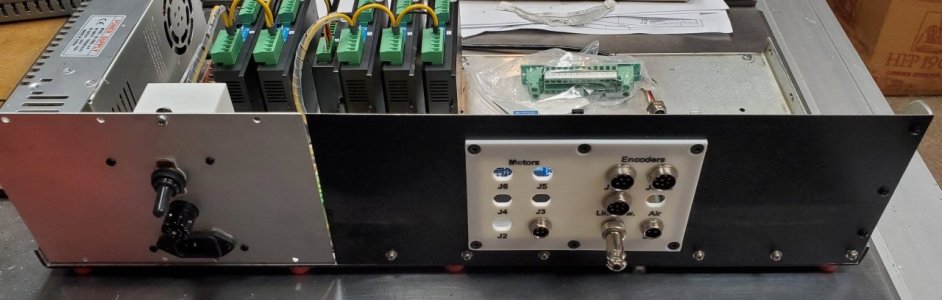
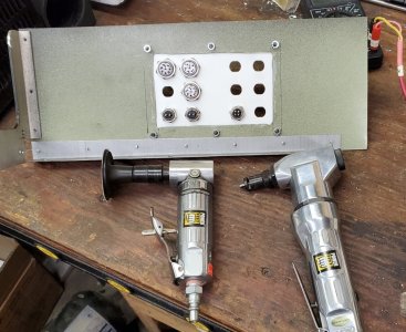
Got the back panel mounted to what will be the back of the AR3 Robot Arm control cabinet. Using as much scrap metal I have on hand to keep the costs down. The back is a piece salvaged from the case of the 35 year old Kitchen Aid Microwave Oven. Support brackets and base from old S100 Computer Case material.

BackCabinet-1.jpg
Every once in a while I luck out. Years ago (like more than 10 I think) I bought these air tools. I've used the little grinder once based on the used sand paper disk. Other than trying out the nibbler it's never been used until now. Not the nicest cutout. I thought about clamping down guides but then thought what the heck let's free hand it.

BackCabinet-2.jpg

Now I no longer have an excuse for not wiring the connectors.
 
Their was a topic about welding just recently. I thought I'd add a link to this video showing some welding. Pretty cool but really only useful for production work where you need to make X units. Otherwise just the work to program it is likely more work than just welding it.


Still pretty cool.
 
To use an old Savoy Brown lyric, “wouldn’t it be a real drag if we were all the same”. I’m slowly filling my shop with manually-powered drills, contemplating assembling a treadle-powered scroll saw, and @jcdammeyer is studiously working to make his shop sophisticated enough that all he has to do is think of a project and his robot army makes it so. I guess it all balances out…
 
Back
Top