• Scam Alert. Members are reminded to NOT send money to buy anything. Don't buy things remote and have it shipped - go get it yourself, pay in person, and take your equipment with you. Scammers have burned people on this forum. Urgency, secrecy, excuses, selling for friend, newish members, FUD, are RED FLAGS. A video conference call is not adequate assurance. Face to face interactions are required. Please report suspicions to the forum admins. Stay Safe - anyone can get scammed.

Installing a digital tachometer

Can you post a link to the one you bought. please? $13 is about half what I paid on AliExpress!
here’s the listing today


But it was $12 when I bought it two weeks ago. Amazon is the perfect example of predatory pricing.

02E57C62-0A10-4089-B95D-6F27F1940502.jpeg
 
Yes, but.....
VicHobbyGuy said:
Can you post a link to the one you bought. please?
Also from inventory, I must have hundreds of magnets strewn about my shop.


Perfect fit, and no problem tripping the switch at about 3/16” spacing

290B59B7-D7E6-4239-80B7-54A6866307C8.jpeg
 
here’s the listing today

........ Amazon is the perfect example of predatory pricing.
Thanks for that link - Yes, I have noticed that before on Amazon - Like most corporations, they treat their regular customers badly. (I learned that lesson years ago from my mortgage holder/bank :"Transfer your mortgage to us and we'll give you a TV!" "But I've been your customer for years and I've been paying off my mortage with you for 13 years!! What about me??" "Sorry..."

I decided to support only one evil empire, not two, and just re-ordered from the same seller on AliExpress. Same price, and I can wait, and the last one worked OK.
 
Also from inventory, I must have hundreds of magnets strewn about my shop.
They are excellent for holding chuck keys on the drill press and clapping to screwdriver shafts, too.

Perfect fit, and no problem tripping the switch at about 3/16” spacing
Just make sure that it's oriented with the correct face toward the sensor! I just realized that when reading this discussion thread and then on tthe web. I thought it was a case of : "Weird; this magnet works but that one doesn't...." when I was putting the tach on my drill press.
 
@whydontu a beautiful morning here in Saskatchewan, just wished my lovely wife of 63 years happy anniversary. Yup tied the knot May 23 1959 here in MJ.

Out to my shop, measured the wrench slots on the spindle nut which comes out somewhere like 1/4 " - 6mm square perhaps a hair under. Tight area to do any kind of serious measurements.

Then I go on line to amazon.ca enter 'square magnets' searching for 1/4 "/ 6mm square magnets without success. Most likely I'm not providing the words key for their search engine also tried square earth magnets, small and mini magnets and rectangular magnets, assorted magnets etc. Loads of round magnets, assorted magnets, found zip in my search at least they didn't bubble to the top.

Open to suggestions folks.
did you get married when you were in kindergarten?
 
@whydontu said 'did you get married when you were in kindergarten?'

Good one! LOL

Tried twice to create an account with Michaels, assume they shut down their computers due to the Vic holiday. Shall try again tomorrow.
 
@Dusty I cannot remember where I saw it but I thought this was a good way to mount a magnet to a shaft, securely.

The poster took a piece of ABS pipe and turned it to fit snugly on the shaft. He then drilled a hole in it to accommodate the magnet flush. He then turned another piece of ABS and slid it over top of the first piece and a couple of drops of crazy glue to keep it in place. The cover sleeve needs to be thin enough to allow the spacing for the magnet but this should not be too hard. The magnets previously mentioned are strong enough. This method insures the magnet will not fly off. If everything is a slight push on fit, you should be good. And a nice little turning project with plastic.

2 cent Shawn
Was it this guy?

 
@whydontu , magnet update, Tuesday afternoon (May 24) I ordered 3 packages of the magnets from Michales (Vancouver store) as per your post #42. Moments ago (Thursday May 26) my wife picked up a rather large box (12"x12"x12" a huge over kill with packaging) from our post box with three packets of round magnets inside. Tried one in my spindle nut wrench slots and it's a snug perfect fit, now I can forge ahead with my digital tachometer installation.

Bottom line that's the best delivery service I've ever received in all my years, thanks to Michales. WOW!!
 
Last edited:
Thought you wanted square?

But glad the round ones fit and glad you are happy.

Safety first and always in my shop.

My preference was to use square magnets then I settled on the 1/4" diameter round ones so I could move on with my lathe upgrade. Must say these magnets are really strong for their size.

My lathe's gear compartment has tight quarters around the spindle and gear set area so one could very easy damage something while running. Should this idea not pan out I'll move on to something else without hesitation.
 
Last edited:
Safety first and always in my shop.

My preference was to use square magnets then I settled on the 1/4" diameter round ones so I could move on with my lathe upgrade. Must say these magnets are really strong for their size.

My lathe's gear compartment has tight quarters around the spindle and gear set area so one could very easy damage something while running. Should this idea not pan out I'll move on to something else without hesitation.
Done. My tach is 120VAC, so I was able to snake the power through the hole at the bottom of the cover into the power switch box.

The sensor bracket is part of a pile of leftover Ikea bits.

Minor cleanup and cable clips still to be done. Next step is quick-change gears for power feed.

72742A5F-C2D8-4224-A54F-7813C9B8D10D.jpeg
 

Attachments

  • 98F94E0D-E3E5-450A-B923-C93BBC893479.jpeg
    98F94E0D-E3E5-450A-B923-C93BBC893479.jpeg
    533.5 KB · Views: 7
  • 38A45F16-4191-4775-BAAF-B2AFA311C361.jpeg
    38A45F16-4191-4775-BAAF-B2AFA311C361.jpeg
    488.8 KB · Views: 7
here’s the listing today


But it was $12 when I bought it two weeks ago. Amazon is the perfect example of predatory pricing.

View attachment 24060
Hmm I like that one better than the one I have which I think requires 12v CD power.
 
Done. My tach is 120VAC, so I was able to snake the power through the hole at the bottom of the cover into the power switch box.

The sensor bracket is part of a pile of leftover Ikea bits.

Minor cleanup and cable clips still to be done. Next step is quick-change gears for power feed.

When it comes time to do mine, it will be child's play.

Here is the back of my lathe head.

20220527_140020.jpg


The black pipe leaning against the cover bolt is 2" ABS with a measured ID of 2.04. The spindle OD itself is 2.07". A wee tiny skim off the inside of the ABS and it will be a friction fit right over the spindle. 1, 2, 3, or 4 holes drilled in the ABS and some magnets the right size glued in and the spindle sensor system is done. I can make a little holder bracket to attach to the two cover bolt screws to hold the sensor itself, and Bob's your uncle!

I may wire it up some day soon just to get a jump start on it, but the final product will have to wait till I buy and then install the DRO. And that in turn will have to wait till I buy and install a VFD and VFD Rated Motor for the lathe

Too many projects! WAY too much fun for an old man. Life is sooo awesome!
 
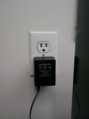
@whydontu & @conbustableherbage - finally I now have my digital tachometer up and running although not without a bucket of problems, read on. Tools required, one brain, pencil soldering iron, volt meter and a life time of patience as I'm not into electronics other than the simple basics. My installation is semi wired across the inner top of the gear cabinet coming out at the upper rear where it connects to a 4 pole mini connector. System designed so I can quickly remove the power supply (120V -12VDC-500MA) and sensor wires from the RPM meter which sits nicely (using magnets) on top rear of the head stock. While machining I won't need to lift my old eyes far from the job at hand to catch the numbers.

Bugger it didn't work, what gives with that? Triple checked my soldered connections now covered with shrink tube with no issues there. Although the sensor and RPM display are lit up with a single digit far right there's no joy when running my lathe so I double check the position of the magnet.

Without going into my frustrations trying to resolve said issue(s) which all boiled down to a wonky digital display/card? Thankfully when I ordered this kit I actually bought two. Changed the RPM meter digital screen and we have lift off, perhaps not quite. When running my lathe the digital display was jumping all over the map so to speak so I added rather stacked another same type magnet on top of the first one sitting in the spindle nut wrench grove. That settled things down some although I believe I can fine tune the clearance between the magnet and sensor a blonde hair more and see if that helps.

Change speed chart on my Craftex B2227L lathe face plate shows the following speeds which I understand are incorrect from factory.
Upper row: 550 - 970 - 1620 RPM, on average my digital sensor reads 600 - 1060 - 1530 RPM
Bottom row: 115 - 210 - 350RPM, on average my digital sensor reads 380 - 460 - 760 RPM
Notes: RPM is more consistent at slower speeds than higher ones.

As for magnets I tried the one that came with the kit with poor results. Switched to a much bigger/stronger one where it simply migrated across the the two spindle lock nuts rubbing on the spindle housing at all speeds. Promptly gave that idea up.

Bottom line am I satisfied hell no, comparing my lathe digital readout to the one on my hobby mill the mill wins hand down for being consistent at all settings.

Photo's:
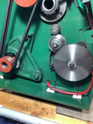
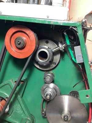
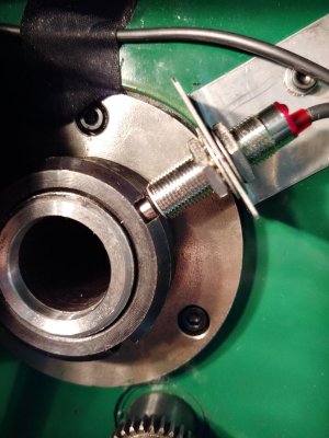
1. sensor installation (single magnet in spindle nut)
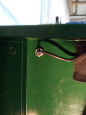
2. upper left rear, gear cabinet wires.
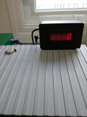
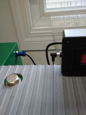
3 & 4. Digital display box, quick disconnect wires through cabinet from sensor and power supply.
5. Digital display sitting idle. To the left, yes that's my head stock gear oil fill access modification.
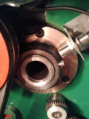
6. sensor installation, stacked double magnets.

Suggestions welcome!!
 

Attachments

  • 20220530_104317.jpg
    20220530_104317.jpg
    163.7 KB · Views: 10
  • 20220530_104302.jpg
    20220530_104302.jpg
    140.3 KB · Views: 10
  • 20220530_104213.jpg
    20220530_104213.jpg
    149.4 KB · Views: 9
  • 20220530_103913_Burst01.jpg
    20220530_103913_Burst01.jpg
    137.4 KB · Views: 10
  • 20220530_103621_HDR.jpg
    20220530_103621_HDR.jpg
    259.4 KB · Views: 10
  • 20220530_144646_Burst01.jpg
    20220530_144646_Burst01.jpg
    193.7 KB · Views: 10
Last edited:
@whydontu & @conbustableherbage - finally I now have my digital tachometer up and running although not without a bucket of problems, read on. Tools required, one brain, pencil soldering iron, volt meter and a life time of patience as I'm not into electronics other than the simple basics. My installation is semi wired across the inner top of the gear cabinet coming out at the upper rear where it connects to a 4 pole mini connector. System designed so I can quickly remove the power supply (120V -12VDC-500MA) and sensor wires from the RPM meter which sits nicely (using magnets) on top rear of the head stock. While machining I won't need to lift my old eyes far from the job at hand to catch the numbers.

Bugger it didn't work, what gives with that? Triple checked my soldered connections now covered with shrink tube with no issues there. Although the sensor and RPM display are lit up with a single digit far right there's no joy when running my lathe so I double check the position of the magnet.

Without going into my frustrations trying to resolve said issue(s) which all boiled down to a wonky digital display/card? Thankfully when I ordered this kit I actually bought two. Changed the RPM meter digital screen and we have lift off, perhaps not quite. When running my lathe the digital display was jumping all over the map so to speak so I added rather stacked another same type magnet on top of the first one sitting in the spindle nut wrench grove. That settled things down some although I believe I can fine tune the clearance between the magnet and sensor a blonde hair more and see if that helps.

Change speed chart on my Craftex B2227L lathe face plate shows the following speeds which I understand are incorrect from factory.
Upper row: 550 - 970 - 1620 RPM, on average the digital sensor reads 600 - 1060 - 1530 RPM
Bottom row: 115 - 210 - 350RPM, on average the digital sensor reads 380 - 460 - 760 RPM
Notes: RPM is more consistent at slower speeds than higher ones.

As for magnets I tried the one that came with the kit with poor results. Switched to a much bigger/stronger one where it simply migrated across the the two spindle lock nuts rubbing on the spindle housing at all speeds. Promptly gave that idea up.

Bottom line am I satisfied hell no, comparing the digital readout to the one on my hobby mill it wins hand down for being consistent.

Photo's:
1. sensor installation (single magnet in spindle nut)
2. upper left rear, gear cabinet wires.
3 & 4. Digital display box, quick disconnect wires through cabinet from sensor and power supply.
5. Digital display sitting idle. To the left, yes that's my head stock gear oil fill access modification.
6. sensor installation, stacked double magnets.

Suggestions welcome!!

I love the install. Very slick and professional looking.

I re-read your post. You talked about the magnet orientation, but isn't obvious to me if you actually tried the magnet upside down.

Regardless, here is a whacky suggestion - try a fatter magnet. At least as big in diameter as the sensor.

Also, many magnetic sensors are sensitive to the gap between the sensor nose and the magnet.

That's all I got.
 
Back
Top