• Scam Alert. Members are reminded to NOT send money to buy anything. Don't buy things remote and have it shipped - go get it yourself, pay in person, and take your equipment with you. Scammers have burned people on this forum. Urgency, secrecy, excuses, selling for friend, newish members, FUD, are RED FLAGS. A video conference call is not adequate assurance. Face to face interactions are required. Please report suspicions to the forum admins. Stay Safe - anyone can get scammed.

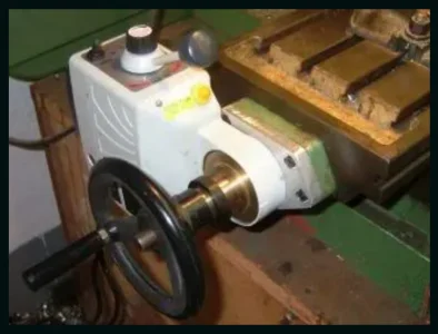
I bought the cheapest Y axis power feed I could find for my milling machine.

Both ends of the screw measure 17mm in dia.

The left side projects 60mm out from the mounting bracket and the bracket is 15mm thick.

The right side projects 80mm out from the mounting bracket and the bracket again is 15mm thick.

If that makes any sense...….

Super, that makes perfect sense.
 
Here's another example
Screen Shot 2021-01-17 at 7.27.02 PM.webp
 
I used the Y axis power feed for the first big job today. I am very pleased with how it operates. I was able to achieve a better surface finish than I have in the past when making the same part. A worthwhile addition I think.
 
I don't see much difference compared to the Align brand one I bought a couple of years ago. I paid more than $400 including shipping for that one but it was for the z axis and needs more power to lift the knee I think.
 
I just found this series.
Pretty much a tutorial on how to do it.
I need to figure out how much vertical height I need. Would you measure from the midline of the shaft to the bottom of the unit for me?
 
Being mounted on a stand why is vertical height a concern?

I’m planning to build a new stand which will be wider than the base and I want to know how much clearance I need between the lead screw and the top op the stand.
Give the video a watch and the reason will be clear :)
 
I’m planning to build a new stand which will be wider than the base and I want to know how much clearance I need between the lead screw and the top op the stand.
Give the video a watch and the reason will be clear :)

Hmmmm…… I wonder what it would cost to ship your stand to Calgary?
 
I just watched Lee's video. There are a couple of things I would do differently but he proves it can be done. The instructions don't cover it well but those thin shims he showed are selective and designed to positively control the backlash between the pinion and the brass bevel gear so no matter how tight the nut is on the end of the shaft, the lash will not change. I would have made an extension for the shaft so the micrometer scale and handwheel could be installed as well as a cover to keep chips out of the gears.
 
I just watched Lee's video. There are a couple of things I would do differently but he proves it can be done. The instructions don't cover it well but those thin shims he showed are selective and designed to positively control the backlash between the pinion and the brass bevel gear so no matter how tight the nut is on the end of the shaft, the lash will not change. I would have made an extension for the shaft so the micrometer scale and handwheel could be installed as well as a cover to keep chips out of the gears.
I agree, I would have made the extension longer to accommodate the dials. Seems a shame to leave them off.
I also noticed the lack of cover on the gears, looks like a swarf trap in the making. I wonder if a cover could be turned from aluminum?
 
Back
Top