Doggggboy
Ultra Member
The same on my little 11 by 36 Taiwanese. Leadscrew is 3/4 inch.The thread dial gear on my lathe has 24 teeth and my leade screw is 8tpi
The same on my little 11 by 36 Taiwanese. Leadscrew is 3/4 inch.The thread dial gear on my lathe has 24 teeth and my leade screw is 8tpi
The same on my little 11 by 36 Taiwanese. Leadscrew is 3/4 inch.

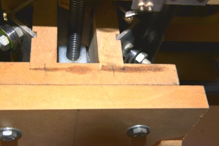
The key thing is that he 3D printed a gear that is fairly close and then let the lead screw on the lathe do the final shaping on the teeth. IOW, the printed gear had the typical tooth profile for a worm system. He mounted that on the lathe and pressed the new gear into the spinning lead screw. The lead screw has the keyway which acts like a single tooth cutter. Since the profile was 'pretty close' to start with, it only required a minute or so of fettling to end up with a gear that works pretty well.
If a fellow wanted to try to turn a worm gear himself to match your leadscrew better, here is a simple method that may be good enough for such a job.
This is one of the shorter videos and just shows the basic process, there are longer more detailed videos out there if anyone is interested.
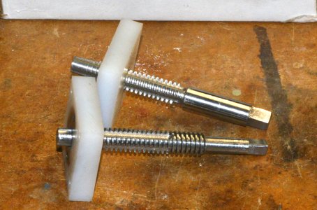
Making a 20mm 8tpi tap would be a fun project
Do you agree, To cut a nylon gear it wouldn't need to be tool steel, an old grade 8 bolt would work. It wouldn't need a lead-in taper to cut a gear and it would only need 1 flute?

My thought was to use a bolt larger than 20mm and turn to size then make a hss threading tool to cut the threads. Then cut the flutes in the mill. The threads are likely metric buttress not acme so grinding a custom tool would be necessary
Mine is 22mm 8tpi but not a 60 degree thread


Acme is 29 degree and Metric trapezoidal thread is 30 degree but looks like acme but of course acme does not have metric sizes so I don't know what to call it.
I started with the 1/2" ACME all thread. OD is 0.497" for the 10 TPI stuff. The one I made has an OD of 0.506" and in the plastic just cut that little bit deeper and smoother as the rolled ACME all thread has a ridge in the middle of the crest of the tooth.What size is the acme tap?