• Scam Alert. Members are reminded to NOT send money to buy anything. Don't buy things remote and have it shipped - go get it yourself, pay in person, and take your equipment with you. Scammers have burned people on this forum. Urgency, secrecy, excuses, selling for friend, newish members, FUD, are RED FLAGS. A video conference call is not adequate assurance. Face to face interactions are required. Please report suspicions to the forum admins. Stay Safe - anyone can get scammed.

Fusion 3D Trials & Tribulations

Susquatch

Ultra Member
Administrator
Moderator
Premium Member
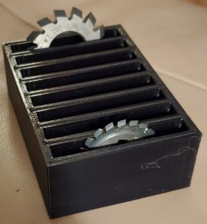
Since then it's printed scores of useful shop stuff like the collet rack I posted. Zero CAD skills needed for that.

You zoomed right in on my other barrier to entry for 3D Printing.

Unless I am wrong, I understand that I need working CAD to be able to customize designs before printing. Everything I know says you need both 3D CAD and 3D Printing. They go together.

I think @jangers on-line group session will either make me or break me - assuming I can even get a connection working. A few members have also offered to help me. But I think I need more help than I feel comfortable accepting.

It's so funny because I've always thought of myself as a change maker - a fellow who embraced change - an early adopter. But Hobby style 3D CAD isn't going so well. And it's not like I've never done it before! I used a corporate 2D CAD system for years and then adopted CATIA 3D with relative ease. I even taught classes to new designers. I also used EasyCad 2D and AutoCAD 2D at home for decades but never transitioned to 3D at home. Mostly cuz I just didn't need it. 2D always met all my needs.

I feel like I'm just missing something very simple - like you have to install a driver before you can do anything. Or a car doesn't work without gasoline.

I'm sort of caught at the transition between sketches and components. EasyCad was 2D only. Catia is 3D solids only. There is no in between. But my sense is that Fusion is an in-between product. You start with a 2D sketch and then morph that into 3D. I can't seem to bridge that simple gap. Stuff I sketch doesn't form right when I extrude it or shape it. Maybe just a simple settings problem.

Sorry to pollute your thread with all this. I should really move it to someplace more appropriate.
Not to worry about polluting my thread; seems we do thread creep here really well ;)
Like you I really struggled with 3D CAD. What changed it for me was Alibre Atom 3D. I don't know why but I was able to grasp the ideas better there than in Fusion 360. Now that I have some basics under control I can more easily work in Fusion 360.
I know that Youtube is not for you but watching tutorials was also a major help to me. Reading manuals just doesn't work for me.
One big challenge I have in 3D design is that I can imagine the end result that I want but I lack the vocabulary to translate that into software functions.
But I realize that it's a learning process so I keep at it.
 
One big challenge I have in 3D design is that I can imagine the end result that I want but I lack the vocabulary to translate that into software functions.
But I realize that it's a learning process so I keep at it.

Are you suggesting I try Alibre first?

Yes, I understand your point about the vocabulary. I can do 3D in my mind really easily too. That's actually how Catia worked. You picked a basic solid shape and then sort of "machined it" or "married it" with other solids into what you wanted. The software could print 2D drawings, but you generally didn't bother. Instead you sent Catia files and a prototype. If a supplier couldn't work with Catia you either got a different supplier or sometime sent them a 3D printed prototype they could section or draw themselves the old fashioned way. That's back when a very simple printer cost a half million and had its own office...... LOL!

Some on here might laugh at the very first 3D printer I used that cut paper and then stacked it with a resin binder between layers - we actually assembled entire engines with parts made that way. Or the first resin machines that used a laser to solidify a layer at a time in a big tub of resin. 3D printing has come a long way from those days. But I digress.

I have done a few parts in Fusion already. Eg stand-alone parts like brackets for my DRO.

Right now I'm stuck on parts with multiple components.

I've been working on a lathe stop for months. I could do the stop itself, but I want it to be part of an assembly - lathe ways, screws, plates, and indicator. It's all stuff I could just make and be done with it. But I'm being deliberately stubborn about forcing myself to bring Fusion under control. I want a lathe stop pretty badly so it's a good incentive.

I'm also going to send a starter design of the lathe stop to @StevSmar who offered to look at it. It's about as simple as it gets. For now, it's just a simple block that sits on the latheway. I don't even have holes or slots on it yet.

I started with the lathe bed, and then put the block on it. What a mess....... Months of pain, rewinds, and start overs. So simple but so far away.

I'll try watching a few more beginner videos......
 
If you've done simple parts then you are well on your way in my opinion. I have not done an assembly in Fusion or Alibre. But I am trying to model the carbide grinder so I'm definitely on the assemble path.

You can download a trial copy of Alibre and see if it suits you. I know it did for me.
 
If you've done simple parts then you are well on your way in my opinion. I have not done an assembly in Fusion or Alibre. But I am trying to model the carbide grinder so I'm definitely on the assemble path.

You can download a trial copy of Alibre and see if it suits you. I know it did for me.

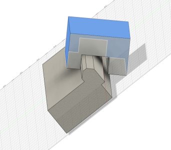
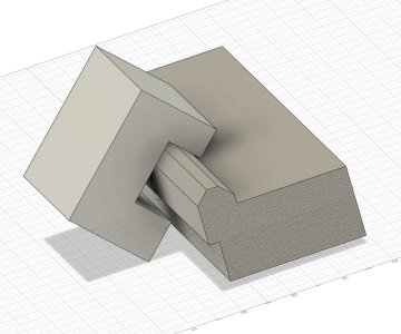
Here is where I am on the lathe stop. The problem is that Fusion won't separate the two parts. I used the "split body" command but no joy.

Lathe Stop.jpg

You can see here that the part has surfaces and is not solid.

Lathe Stop Rear.jpg

I have downloaded Alibre. But I haven't installed it yet. I will if I can't get past this log jam.
 
I can go into my long story with respect to my CAD issues. But simply put once I bought Alibre 3D CAD and parametric drawing was suddenly easy for me. Not that there isn't a learning curve but as yet I never did do anything of value in Fusion360, FreeCAD or Mecsoft CAD.

@David_R8 sent me the STP file of his drawing because his Rev27 creates drawing files that can't be read by REV25. But I imported his STP file and added a support feature to make printing easier. Then saved as an Alibre PART file Rev25 which he will be able to read.
 
Here is where I am on the lathe stop. The problem is that Fusion won't separate the two parts. I used the "split body" command but no joy.

The only way i know that this command works is if you create an offset construction plane, then you can split the body through that plane (offset plane is under "construct" on the top tool bar)

do you have two bodies in the sidebar ? im guessing when you extruded the second piece that you selected "join" vs "new body" ?

I don't remember how I did it. This project has been months in the works. I dropped it out of frustration several months ago and now I'm back at it. I either learn Fusion (or Alibre) or I forget about getting a 3D Printer.

What is most frustrating is that i could have whipped this project out in just a few hours without anything but what is in my head.

I'll need to research "offset construction plane".

How do you stop a plane that intersects several parts from including them? Is there an include / exclude command?

Why is the block transparent looking through the backside but not from the front? It looks to me like it's a collection of surfaces with a hollow interior instead of one solid body.

Maybe my example part was a bad idea. It is the result of many iterations - some of which might not be reversible.

Perhaps it would be better to start fresh with some dimensions. I'll start a new thread after supper tonight and move everything there.
 
Here is where I am on the lathe stop. The problem is that Fusion won't separate the two parts. I used the "split body" command but no joy.

View attachment 41849

You can see here that the part has surfaces and is not solid.

View attachment 41850

I have downloaded Alibre. But I haven't installed it yet. I will if I can't get past this log jam.
Can you send me this file as is ? I would like to have a look at it. PM for email..
 
I don't remember how I did it. This project has been months in the works. I dropped it out of frustration several months ago and now I'm back at it. I either learn Fusion (or Alibre) or I forget about getting a 3D Printer.

What is most frustrating is that i could have whipped this project out in just a few hours without anything but what is in my head.

I'll need to research "offset construction plane".

How do you stop a plane that intersects several parts from including them? Is there an include / exclude command?

Why is the block transparent looking through the backside but not from the front? It looks to me like it's a collection of surfaces with a hollow interior instead of one solid body.

Maybe my example part was a bad idea. It is the result of many iterations - some of which might not be reversible.

Perhaps it would be better to start fresh with some dimensions. I'll start a new thread after supper tonight and move everything there.

i would also need the file, you can email it to me if you like

but my first though to split that block would be to use "plane through 3 points" it is under construct
 

Susquatch

I teach F360 at the local university as part of the digital manufacturing program. Students start with the basics - 2D drawings -> Isometric drawing -> Extruded solids -> Boolean solids -> 3D sculpting. Thats a 3 week, 9 day course which gives the class the foundation skills necessary before we look at 3D printing and CNC machine work. Built into that course are basic design principles, materials, fasteners, DFMA, etc. so the engineering concepts of stress concentrations, mass and stiffness are introduced early and put into practice later. The training is straightforward and intended for first-time users of CAM systems.

F360 is not a drawing system (although it can produce engineering drawings) and I think if you are approaching it from that perspective it will be a struggle to get into the flow.

I'd be happy to work with you over zoom for example, for a couple of hours to get you launched properly so you would be ready for John's sessions.

Don
 
I'd be happy to work with you over zoom for example, for a couple of hours to get you launched properly so you would be ready for John's sessions.

Seems like there are a lot of folks who are willing to help. That's a great testament to the success of our forum and the caliber of our members.

I am going to send those who offered to help, a link to this particular design file by PM.
Lets see how far we can get using that approach. You can feel free to help via that pm, but I think it would better to do the teaching and learning here instead so that other members who might need help can find it and benefit too.

@Arbutus - see post above regarding my CAD experience. You need not worry about my perception of Fusion. I've spent the better part of 40 years learning to do CAD drawings and then CAD solids with Catia. So I understand your points.

As an engineer who worked in both Industry and in academe, I can also appreciate the engineering fundamentals you require in your course. I confess that I am both surprised and pleased to learn that at least one university in Canada has successfully departed from the standard degree credit course model to include CAD in their CEAB Accredited Engineering Programs. I had to fight very hard to get that kind of approval through the system back in my day.
 
Open questions:

1. How do you configure Fusion 360 when you first install it? Are there any configuration options that need to be set ahead of time so that subsequent work is not fettered by the initial setup?

2. How do you configure a new design when you first start? Are there any configuration options for each individual design that need to be set before adding design elements so that subsequent work on that design are not fettered by the initial setup for that particular design?

@Janger - you might consider these two questions as you layout your planned group session.
 
1. config on first install. Not especially. A few things you may want, default units (imperial, metric). Maybe the grid spacing and visibility. Perhaps the graphics card setup in preferences. Mouse settings. Important to get zooming, panning, and spinning figured out how they work with the mouse or trackpad so you can be productive. The mouse one is a good one to go over.

2. configure new designs. What is the right name for your model and where (what folder, do you need a separate folder?) are you going to save it. If you decide to create separate design files for individual components then a folder is nice to keep it all together.
 
MAJOR NEWS FLASH - I downloaded and installed a Fusion software update for other reasons. I now notice that the Lathe Stop and the Bed Ways are two separate bodies. I can hide one or the other just by clicking on them in the side menu.

My newbie take is that there was a bug in the software that they have fixed. All my pain was for naught.

Sorry for causing so much confusion and trouble but a HUGE THANK YOU to all those who reached out to me to try to help! It is appreciated more than you might guess.

Im going to complete the stop now and then decide if I want a 3D printer or not and what printer to get after Christmas.

But definitely running out of excuses to avoid buying a 3D printer.......

I hope those with access to my design files continue to watch over me. I don't think for one minute that this is my last issue.....
 
The thing to do next is export the file as a .stp file and send it to someone nearby who does have a 3D printer. Then they can run it off for you to see if there are any issues.
When I popped in on @David_R8 yesterday with the sample cutter holder box we discussed how designing for 3D printing is also different than designing for machining or wood working.
 
When I popped in on @David_R8 yesterday with the sample cutter holder box we discussed how designing for 3D printing is also different than designing for machining or wood working.
John, pease elaborate on some conclusions you and David have drawn on designing for 3D printing. I'd like to know more about what you both were thinking.
 
You zoomed right in on my other barrier to entry for 3D Printing.

Unless I am wrong, I understand that I need working CAD to be able to customize designs before printing. Everything I know says you need both 3D CAD and 3D Printing. They go together.

A couple of points to consider:

+ it seems there is a step file for almost everything these days, so often for trial fit you can print things that will be a part of what you are building with no CAD program or need to use it. I do this for things like bearing blocks, shaft couplers etc. A step further integrating these models into a simple design, for example a simple mounting plate with a bearing block takes very little skill, easy to make a simple rectangular plate and then you just add the more complex part that someone did all the hard work developing.

+ I don't know how to use Fusion or any similar program, however the PCB software I use (Altium) has 3D capability that is very easy to use. That's all I have been using. So perhaps you can leverage some other software that you are already familiar with. With Altium you can make the shape of the PCB anything you want and you can set the thickness to anything you want, a through-hole pad becomes a drilled hole. So I can make a shape and then save that thing as a step file. I can then make a more complex part by just merging the various step files and saving them as a step file. I can rattle off a simple part in minutes using this technique. Yesterday I needed a simple mount for a power supply. A few measurements later I had my simple model and off to the printer.

In the example shown below, the base was just a rectangular PCB, with 4 pads (mounting holes), I added little edges using the create extrusion feature. Then I made another simple PCB shape for the four little tabs, simple rectangle shape with a slot for the tyrap. I then added four of the "tab" step files to the original (oriented at 90 degrees) and placed appropriately. Point is you can start with really simple shapes.
A3345CD5-3C43-4367-8E58-31CDF4BE085C.jpeg
 
Last edited:
John, pease elaborate on some conclusions you and David have drawn on designing for 3D printing. I'd like to know more about what you both were thinking.
Wall thickness for example. Although a machined or sheet metal box might work well with 1mm thick walls 3D printing is too thin and it's fragile and can warp.

Support while printing. Or just design so the support is built in. And is it printed right side up or down and if so how to add support.

When we build for metal we can get away with a threaded hole in material that is the thickness of a standard nut. Holes that are 3D printed are generally just concentric circles and aren't well melted together so designing for a thicker area for screws. Ether to be tapped or trying to make threads (usually doesn't work well). Or instead create a circular and then hex hole that doesn't go all the way through and epoxy in a nut. We do that in woodworking but rarely in metal working.

For example. Here's the first try at the cutter holder box viewed from the bottom. Meant to be printed from the top side. The walls are so thin that the printing of the curves creates gaps because the curve is changing faster than the thickness of the layers.
1703181067220.webp


I added a support since the curved parts didn't reach the bottom and tried printing it with the box sitting upright.
1703181381608.webp

I still had issues even after I added fillets.
Since @David_R8 uses Alibre ATOM Rev 27 I can't read the design files into my Alibre Expert 25 or 26 I used the dimensions from his box and started over.

I used thicker walls when I created the shell under the curved slots. Now the space between the slots is filled. Then I added a plate on the bottom and cut out two rectangles and added the fillets. Now instead of 1.5 hours it takes 4.5 hours to print.

1703181721706.webp


While printing in black it appeared to have a flat are at the bottom of each slot. So I sectioned the drawing. It shows a side effect I didn't expect. The fillets appeared to be cutting away part of the curve. Turns out it wasn't just the fillet but the plane and the inserted flat section.
1703181863055.webp


I played around a bit more with the thickness of the flat section, plane position and fillet radius.

1703182050331.webp


Now it's what I want and I can print it right side up so that when it sits on a shelf or drawer it will sit flat since it was printed this way on the build plate.

None of this would be an issue with it built out of metal because we'd never design it to have this type of cavity on the bottom. Maybe flip it over to create some slots so it would be lighter but that's just extra milling time with no real purpose.

And now the CURA slicer properly fills in the gaps with 20% infill. This section is at layer 33 out of 175.
1703182627929.webp
 
Back
Top