-
Scam Alert. Members are reminded to NOT send money to buy anything. Don't buy things remote and have it shipped - go get it yourself, pay in person, and take your equipment with you. Scammers have burned people on this forum. Urgency, secrecy, excuses, selling for friend, newish members, FUD, are RED FLAGS. A video conference call is not adequate assurance. Face to face interactions are required. Please report suspicions to the forum admins. Stay Safe - anyone can get scammed.
-
Several Regions have held meetups already, but others are being planned or are evaluating the interest. The Calgary Area Meetup is set for Saturday July 12th at 10am. The signup thread is here! Arbutus has also explored interest in a Fraser Valley meetup but it seems members either missed his thread or had other plans. Let him know if you are interested in a meetup later in the year by posting here! Slowpoke is trying to pull together an Ottawa area meetup later this summer. No date has been selected yet, so let him know if you are interested here! We are not aware of any other meetups being planned this year. If you are interested in doing something in your area, let everyone know and make it happen! Meetups are a great way to make new machining friends and get hands on help in your area. Don’t be shy, sign up and come, or plan your own meetup!
You are using an out of date browser. It may not display this or other websites correctly.
You should upgrade or use an alternative browser.
You should upgrade or use an alternative browser.
Fusion 360 Fastener library
- Thread starter Janger
- Start date
I’ve heard of this and it’s a red flag on used motorcycles. I don’t understand how the wire locks the bolt in exactly? The wire is put through the bolt head and then … tied to a post? Got any photos?Allen head screws that are drilled horizontally are not rare in my line of work. The holes are so that they can be safetied with lockwire after installation. I work in aviation but I have seen them on motorcycles too.
Part number for them begins with MS24673.
I’ve heard of this and it’s a red flag on used motorcycles. I don’t understand how the wire locks the bolt in exactly? The wire is put through the bolt head and then … tied to a post? Got any photos?
The wire is put through the bolt or screw in a way that if you pulled on the wire it would pull it tighter and not looser. Usually they are tied off to another bolt or screw. They may be wired to a drilled hole if they are a single bolt. Allen head screws are usually safetied using a single wire method. Bolts use a double wire in that the wire is twisted.I’ve heard of this and it’s a red flag on used motorcycles. I don’t understand how the wire locks the bolt in exactly? The wire is put through the bolt head and then … tied to a post? Got any photos?
You can see pictures of safety wires dating back to the very first aircraft engines. Pretty much any application where a bit of extra installation effort would prevent a bad day or a catastrophe.
And there are application specific lock wires too
 www.e-aircraftsupply.com
And there are application specific lock wires too
Lock Wire | Lockwire | Aircraft Lock-wire | MS20995C32
Jaco Aerospace, the nation's lockwire leader, stocks all types, alloys, finishes, and sizes of lockwire, including lockwire installation tools and custom lock wire labeling.
www.e-aircraftsupply.com
Thanks for the posts. The idea is to keep the bolt from loosening and coming out ok. And is it also to keep the bolt from going flying? Maybe both?
Installation seems tricky and critical for keeping the bolt from loosening. A taut wire well anchored is needed?
Installation seems tricky and critical for keeping the bolt from loosening. A taut wire well anchored is needed?
The purpose is to keep the bolt from loosening and losing torque. It may fall out or it may cause assembled parts to pound each other to pieces depends on the situation. While the wire should be tight sometimes you just have to do the best you can. It's easy sometimes and in other cases you are lock wiring in a hole behind a pipe while using a mirror and a flashlight. Ideally the wire should be as tight as you can make it without work hardening the wire and making it brittle. One of my former inspectors said it should be as tight as a banjo string.Thanks for the posts. The idea is to keep the bolt from loosening and coming out ok. And is it also to keep the bolt from going flying? Maybe both?
Installation seems tricky and critical for keeping the bolt from loosening. A taut wire well anchored is needed?
Quick vids on installation.Thanks for the posts. The idea is to keep the bolt from loosening and coming out ok. And is it also to keep the bolt from going flying? Maybe both?
Installation seems tricky and critical for keeping the bolt from loosening. A taut wire well anchored is needed?
This guy has some funky pliers to help. A handle on the the seems to let him spin the pliers to add the twist easily.
All of us being banjo players and know exactly what he means.One of my former inspectors said it should be as tight as a banjo string.

 kidding..
Those pliers are called Lock wire pliers. They are in no way required to do a quality lock wire job. They make it faster not better.Quick vids on installation.
This guy has some funky pliers to help. A handle on the the seems to let him spin the pliers to add the twist easily.
Matt-Aburg
Ultra Member
Yup, preferences options... I would generally only use SHCS, hex bolts or flathead for the most part. I don't know what all the standards mean, just basic imperial or metric.. not ansi.. etc.@Janger - I think the original point is that many of us don't need that kind of stuff polluting our choice of fasteners.
In the absence of favorites, how about simple checkmarks to enable or disable entire categories or subcategories.
Well yes but this lock wire is such an interesting side bar.@Janger - I think the original point is that many of us don't need that kind of stuff polluting our choice of fasteners.

Matt-Aburg
Ultra Member
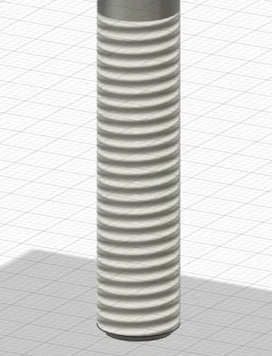
I did use this today to acquire the models into my main CAD system.... what I noticed is that the fusion fasteners appear to have threads on them in Fusion. This is only a graphic projected onto the solid body. Makes for a lighter version since in reality it is just a cylinder..
Attachments
I asked them (AutoDesk) to please add the 'modelled' check box to fasteners as the lighter version does not support 3D printing the threads. You can 3d print threads with parts that have threads added to them in the Hole create command or the thread create command.
Modelled on the left, not modelled on the right.

Modelled on the left, not modelled on the right.
Modelled on the left, not modelled on the right.
Something wrong with the photo John. My phone took 5 minutes to open it.
Very interesting observation. What does that mean for us guys with a hobby version?
It may be obvious but the reason that CAD systems show graphic representations of threads vs actual thread geometry is that the mathematical overhead of the actual geometry is heavy and when you have multiple fasteners or tapped holes you can bring your CAD station to its knees pretty quickly.I asked them (AutoDesk) to please add the 'modelled' check box to fasteners as the lighter version does not support 3D printing the threads. You can 3d print threads with parts that have threads added to them in the Hole create command or the thread create command.
Modelled on the left, not modelled on the right.
View attachment 41979
I get your reason for having real geometry for 3DP and maybe there is or could be a way to satisfy the requirement too. Maybe you could create a personal macro to cut threads in multiple holes?
D
Agree with @Tecnico 100%. Nothing stopping you from having actual threads in parts & assemblies. But if it serves no real purpose other than aesthetics, its presence requires lots of processor chugging for no benefit. Even just working on the model, every time you rotate model to a different perspective, it has to recalculate all that complicated facet geometry. 50 holes = 50X the processing. Think of the CO2! Think of the backstroking polar bears! That's WHY cosmetic threads exist. The hole/thread callout tells you all the details required for machining anyways.
Now to take this a step further when you are MAKING a part with threads, 3DP or whatever, yes now you need the profile. So if the CAD app provides threads via drop down tables, good to go, use them. But if not, or incomplete thread listing (coarse but no fine), or something different (BA or buttress or NPT or watchmaking or whatever) making your own threads isn't al that difficult. If you can draw a Vee & your app can draw a helix profile, you have all the necessary ingredients. Picture example. The thread Vee profile is completely defined with only 3 parameters (light grey just for info). The helix is defined by pitch. Then just cut the Vee profile along the helix. Or in the case of male threads 'add' thread profile along the helix. So you can make pretty much anything & this gives you 100% control. Maybe your 3DP parts needs some different allowance or fillet geometry, or whatever. No-problemo. This isn't time efficient for standard fasteners where you just pick & drop, but just wanted to show, its not so scary.


Here I generalized a metric thread profile calculator using equation driven parameters. Only the few (black) values represent the inputs, the rest (grey) are secondary values I was checking against published tables. This happens to be M10x1.0 but it could be anything in the metric fastener library, coarse or fine or whatever.

Now to take this a step further when you are MAKING a part with threads, 3DP or whatever, yes now you need the profile. So if the CAD app provides threads via drop down tables, good to go, use them. But if not, or incomplete thread listing (coarse but no fine), or something different (BA or buttress or NPT or watchmaking or whatever) making your own threads isn't al that difficult. If you can draw a Vee & your app can draw a helix profile, you have all the necessary ingredients. Picture example. The thread Vee profile is completely defined with only 3 parameters (light grey just for info). The helix is defined by pitch. Then just cut the Vee profile along the helix. Or in the case of male threads 'add' thread profile along the helix. So you can make pretty much anything & this gives you 100% control. Maybe your 3DP parts needs some different allowance or fillet geometry, or whatever. No-problemo. This isn't time efficient for standard fasteners where you just pick & drop, but just wanted to show, its not so scary.
Here I generalized a metric thread profile calculator using equation driven parameters. Only the few (black) values represent the inputs, the rest (grey) are secondary values I was checking against published tables. This happens to be M10x1.0 but it could be anything in the metric fastener library, coarse or fine or whatever.
Last edited:
I forgot to show one little detail that tripped me up initially. The plane that you draw the Vee thread must be perpendicular to the helix. So I just use the helix start point & specify 'pierce' which totally defines it.
You can make springs with a very similar workflow, but that's a different subject.

You can make springs with a very similar workflow, but that's a different subject.