• Scam Alert. Members are reminded to NOT send money to buy anything. Don't buy things remote and have it shipped - go get it yourself, pay in person, and take your equipment with you. Scammers have burned people on this forum. Urgency, secrecy, excuses, selling for friend, newish members, FUD, are RED FLAGS. A video conference call is not adequate assurance. Face to face interactions are required. Please report suspicions to the forum admins. Stay Safe - anyone can get scammed.

Fractional HP motor reversing

I hooked up my multimeter to the switch and it's definitely a problem. It releases intermittently in one direction now and not at all in the other. I've cleaned and polished as much as I can but there still seems to be something not quite right about how the centrifugal switch is set.

I was VERY SPECIFICALLY interested in whether it ENGAGES as the motor spins down. You should hear a loud click as the motor slows down. If you do not hear the loud click, then it prolly never released as it spun up. That would explain the rough motor in that direction.

This is important because we don't want to be chasing a winding problem that does not exist.

In any diagnostic procedure, you have to start by eliminating possibilities so you don't end up chasing your tail.

It's a good bet based on your findings that the centrifugal switch is faulty. But why even bother repairing anything if the winding is also faulty. Motors that size are cheap.
 
I was VERY SPECIFICALLY interested in whether it ENGAGES as the motor spins down. You should hear a loud click as the motor slows down. If you do not hear the loud click, then it prolly never released as it spun up. That would explain the rough motor in that direction.

This is important because we don't want to be chasing a winding problem that does not exist.

In any diagnostic procedure, you have to start by eliminating possibilities so you don't end up chasing your tail.

It's a good bet based on your findings that the centrifugal switch is faulty. But why even bother repairing anything if the winding is also faulty. Motors that size are cheap.
You overestimate my means

But less jokingly, what is a hobby if not chewing over problems you made yourself on purpose?
 
You overestimate my means

But less jokingly, what is a hobby if not chewing over problems you made yourself on purpose?

I hear you. Just power the motor on and then off again a few seconds later, and then listen. The click should be obvious as the nose on your face. No click, and it was always on and never turned off. That's probably why your motor didn't run right. But it could be other things too.
 
Last edited:
I hear you. Just power the motor on and then off again a few seconds later, and then listen. The click should be obvious as the nose on your face. No click, and it was always on and never turned off. That's probably why your motor didn't run right. But it could be other things too.
I haven't heard a click, but I've also run the motor with continuity testing attached to the switch terminals and as I may have mentioned earlier it disconnects intermittently one way and not at all the other 🙁

I'm really scratching my head about how to fix this very annoying problem.
 
@Garzweiler

When I was asking about this motor's history earlier where I was heading was this:

- the way it was originally wired it worked fine? Check.
- make a wiring diagram.
- without adding the reversing switch simply wire it to reverse direction and verify operation. All good? Check.
- make a 2nd diagram.
- add the reversing switch based on the two diagrams.

Maybe too slow and methodical but that's how I would have approached this. Prove it operates fine in either direction before adding the switch.
 
@Garzweiler

If the motor is simply wired to run one direction, reversing switch removed, and the centrifugal switch is still acting up there is a lot of detailed information regarding centrifugal switches in the book I referred to earlier. Starting on page 354. Lots of information on inspecting, maintaining, and troubleshooting.
 
Send a PM to @BaronJ. He might be able to email you a copy.

I share your view of Scribd. I spent hours a few years ago trying to upload a document only to get a totally useless credit I could do nothing with.
I would love to get a copy myself. Google drive ought to handle this sort of file pretty easily.
 
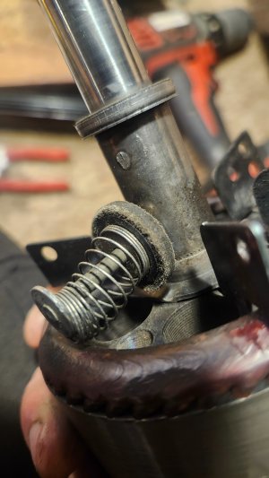
I have recleaned and repolished just about everything and the switch still won't disengage consistently.
 

Attachments

  • 20260829_192543.jpg
    20260829_192543.jpg
    988.3 KB · Views: 8
If it ran fine before it should run fine now, something got disturbed.

How does the motor feel when turning by hand? Does it spin smooth? Does it seem to drag/rub at any point?

With the motor wired as originally found... The switch should open at a certain speed which is ROUGHLY 70-80% of synchronous speed. Do you have anything to measure RPM? If you don't, I believe there are phone apps that can be used for this but I have no experience with them. Do some calculations and see what the approximate range is for your motor. I would keep these tests very short since the motor might be damaged during prolonged running with the switch closed/fluttering.

If it is not reaching a speed that triggers the switch to open and the motor appears mechanically sound double check the start capacitor value. As shown in your picture range is 170-250 MFD (microfarads).
 
If it ran fine before it should run fine now, something got disturbed.

As I recall, it ran fine in forward but not in reverse.

I have recleaned and repolished just about everything and the switch still won't disengage consistently.

Never saw one that looked like that. But it doesn't look fine to me at all. Can you make a collar to keep the spring properly centered? You lift the spring and slip the collar in sideways?

At some point here, I'd pitch that motor and get a replacement.
 
Never saw one that looked like that. But it doesn't look fine to me at all. Can you make a collar to keep the spring properly centered? You lift the spring and slip the collar in sideways?
@BaronJ

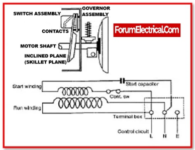
Never seen one like it either. Found an image and some information (had to improve the text otherwise it was similar to the lower wiring diagram):

Skillet style switch.png

Taken from Fractional & Subfractional Horsepower Electric Motors Third Edition:

"17-7. Other Starting Switches. Many forms of centrifugal starting switches have been developed and used. One form, developed by the Ohio Electric Company, had a stationary member consisting of two stationary slip rings, secured to the front end shield and connected inseries with the auxiliary winding; the rotor carried a single brush which spanned the two rings, closing the circuit when the motor was at stand still; as the rotor came up to speed, centrifugal force caused the brush to move radially outward, away from the slip rings, thereby opening the starting-winding circuit. Another quite different arrangement was the skillet type, developed by Delco: the stationary member carried a skillet-shaped arm which bore the stationary switch contacts; the governor weight was washer-shaped and slid along a radial switch pin,against a coil-restraining spring; in earlier models, the switch pin was mounted in a hole in the shaft, but in later models it is supported by a boss or projection which is cast integral with the aluminum end ring of the rotor. Westinghouse has used many forms of starting switches. A number of motor manufacturers still use their own design of centrifugal switches; most of these designs use a phenolic spool, arranged to slide along the shaft to actuate the stator member; the spool is caused to move by weights, moving outward due to centrifugal force, acting through a toggle linkage; the toggle idea, of course, is to make the rotor member snap-acting, for reasons already explained. One such switch is illustrated in Fig. 17-6. Many of the above-mentioned switches were discussed in greater detail in Chap. XVIII of an earlier work."


@Garzweiler

Does any of that look or sound familiar to the motor you're working with? In that diagram above the "governor assembly" looks similar to what you posted.

 
In the 2nd edition "Delco Starting Switches" page 429 (screen shot from an eBay ad):

Delco.png

I would really like to read about how that switch works if I could find a copy online.
 
@BaronJ

Never seen one like it either. Found an image and some information (had to improve the text otherwise it was similar to the lower wiring diagram):

View attachment 86253

Taken from Fractional & Subfractional Horsepower Electric Motors Third Edition:

"17-7. Other Starting Switches. Many forms of centrifugal starting switches have been developed and used. One form, developed by the Ohio Electric Company, had a stationary member consisting of two stationary slip rings, secured to the front end shield and connected inseries with the auxiliary winding; the rotor carried a single brush which spanned the two rings, closing the circuit when the motor was at stand still; as the rotor came up to speed, centrifugal force caused the brush to move radially outward, away from the slip rings, thereby opening the starting-winding circuit. Another quite different arrangement was the skillet type, developed by Delco: the stationary member carried a skillet-shaped arm which bore the stationary switch contacts; the governor weight was washer-shaped and slid along a radial switch pin,against a coil-restraining spring; in earlier models, the switch pin was mounted in a hole in the shaft, but in later models it is supported by a boss or projection which is cast integral with the aluminum end ring of the rotor. Westinghouse has used many forms of starting switches. A number of motor manufacturers still use their own design of centrifugal switches; most of these designs use a phenolic spool, arranged to slide along the shaft to actuate the stator member; the spool is caused to move by weights, moving outward due to centrifugal force, acting through a toggle linkage; the toggle idea, of course, is to make the rotor member snap-acting, for reasons already explained. One such switch is illustrated in Fig. 17-6. Many of the above-mentioned switches were discussed in greater detail in Chap. XVIII of an earlier work."


@Garzweiler

Does any of that look or sound familiar to the motor you're working with? In that diagram above the "governor assembly" looks similar to what you posted.
Oh wow that "skillet type" seems like exactly what I have and it is a Delco. Thanks so much for the research!
 
In the 2nd edition "Delco Starting Switches" page 429 (screen shot from an eBay ad):

View attachment 86254

I would really like to read about how that switch works if I could find a copy online.
need to login to borrow but here is
 
Back
Top