• Scam Alert. Members are reminded to NOT send money to buy anything. Don't buy things remote and have it shipped - go get it yourself, pay in person, and take your equipment with you. Scammers have burned people on this forum. Urgency, secrecy, excuses, selling for friend, newish members, FUD, are RED FLAGS. A video conference call is not adequate assurance. Face to face interactions are required. Please report suspicions to the forum admins. Stay Safe - anyone can get scammed.

Fractional HP motor reversing

Was just getting ready to post some more photos and yes, it has one big honking capacitor strapped to the outside.

Much clearer look under the hood, I think I've been able to identify some things.

Yellow is the two lines off the capacitor, one going into what I infer is the start coil. The Orange line is the other.

Red and green are the primary coil, and the blue terminals appear to be where the centrifugal switch connects.

I've got a 2P2T switch that I was hoping to use for directionality and innumerable other SPST switches for on/off. Just want to make sure I'm connecting the right stuff in the right spots.
Sorry Garzwieler
If its got a centrifugal switch you have got a lot more figuring out to do ! Usually that means that it hasn't got a capacitor and that you actually have to rewire the connections so that the run windings are electrically reversed ! That capacitor if it has one may be between two windings, so you have to be careful that when the centrifugal switch opens it doesn't disconnect the whole motor. That would cause the motor to hunt.

Your changeover switch could be used to swap the run coil connections over.

From the picture it looks like you have the changeover switch correct.
 
This is much more of a pickle than expected! Thanks for all the help, everyone.

I'm positive there is one (and seems to be only one) capacitor as it's hard to miss the giant tube attached to the side.

I should open up some of my other motors to see if they might be more straightforward.
 
I'm positive there is one (and seems to be only one) capacitor as it's hard to miss the giant tube attached to the side.

One capacitor just means it has a start cap and no run cap. So that isn't decisive.

Also, many single caps are really dual caps in the same can. So that doesn't define anything either.

The important thing is that you have a start cap. One of their primary purposes is to set the direction of rotation. Therefore, rewiring the start circuit can reverse the direction - which is what you want.
 
One capacitor just means it has a start cap and no run cap. So that isn't decisive.

Also, many single caps are really dual caps in the same can. So that doesn't define anything either.

The important thing is that you have a start cap. One of their primary purposes is to set the direction of rotation. Therefore, rewiring the start circuit can reverse the direction - which is what you want.
I guess I could test that to see if it's even possible to change direction.
 
Hi Garzweiler,

Using the diagram/picture that I posted shows the basic motor wiring, if you can positively identify which wires and which windings you should be able to figure out which wires you need to swap. Most of the definitive information that I have is no longer available to me.

But fundamentally every motor will have a run winding, a start winding and some way to determine its direction. That may be a capacitor, an inductor a switch, any number of different ways to achieve the same thing.
 
@Garzweiler

Best advice I was given when trying to sort out electrical wiring is "draw it out".

Trace the wires, identify where each one goes (temporarily tag the wires with masking/painters tape - #1, #2, etc), and put it down on paper.

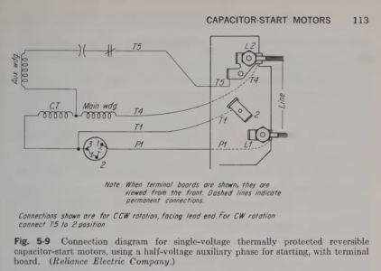
If you open an account here LINK you can view this excellent book that gives a great deal of information to identify the various types of motors and how they are wired. You need to be a little patient as the site will interrupt occassinally with a countdown clock "unlock the next 20 pages after an ad" (about 10 seconds). Once it counts down you can select "skip ad" and move on to continue vieweing the PDF. You can view the Contents (page 15) and then type in the page number to the left of the screen to jump ahead. You will likely want to start on on page 66 - Split-Phase Induction Motors. Here's an example of the type of information and diagrams you will find:

Diagram.png
 
Last edited:
Best advice I was given when trying to sort out electrical wiring is "draw it out".

^^^ This! Except, I was never told that. But it is what I have always done and still do. It works! The confusion becomes clear!

Very nice book. I've never seen it before. I've bookmarked it for future reference. I wonder if it can be purchased?
 
It is available for sale via Amazon, but, it's not cheap.

You can find several copies on eBay as well. Much better prices.

The version I linked to is the 3rd edition from 1986. I seen at least one copy on eBay that claims to be the 3rd edition but the pictures look more like the 2nd edition.
 
@Garzweiler

Best advice I was given when trying to sort out electrical wiring is "draw it out".

Trace the wires, identify where each one goes (temporarily tag the wires with masking/painters tape - #1, #2, etc), and put it down on paper.

If you open an account here LINK you can view this excellent book that gives a great deal of information to identify the various types of motors and how they are wired. You need to be a little patient as the site will interrupt occassinally with a countdown clock "unlock the next 20 pages after an ad" (about 10 seconds). Once it counts down you can select "skip ad" and move on to continue vieweing the PDF. You can view the Contents (page 15) and then type in the page number to the left of the screen to jump ahead. You will likely want to start on on page 66 - Split-Phase Induction Motors. Here's an example of the type of information and diagrams you will find:

View attachment 85973
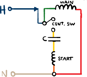
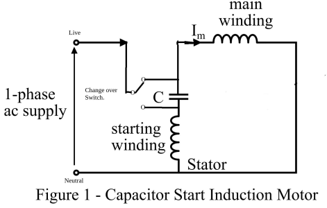
I think what has been tripping me up (no pun intended) has been the involvement of the centrifugal switch. But, I *think* this is the layout of my motor.

Still trying to wrap my head around how to flip the legs of the capacitor back and forth to match the diagram:

1787725123326.png1787725931814.png
 
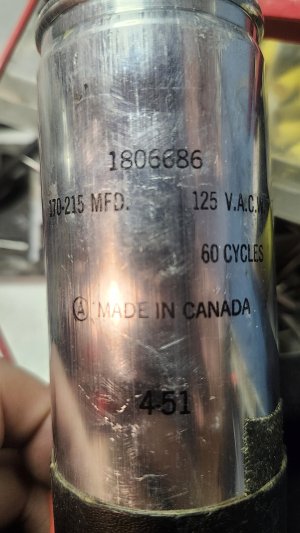
I thought that the simplest way would be to do the switching right at the capacitor itself, so I got busy redoing some wiring - but found that it only seems to have continuity in one direction... Does this mean it's polarized and this is a nonstarter or could it be replaced?
1000094178.jpg
 
Back
Top