
-
Scam Alert. Members are reminded to NOT send money to buy anything. Don't buy things remote and have it shipped - go get it yourself, pay in person, and take your equipment with you. Scammers have burned people on this forum. Urgency, secrecy, excuses, selling for friend, newish members, FUD, are RED FLAGS. A video conference call is not adequate assurance. Face to face interactions are required. Please report suspicions to the forum admins. Stay Safe - anyone can get scammed.
You are using an out of date browser. It may not display this or other websites correctly.
You should upgrade or use an alternative browser.
You should upgrade or use an alternative browser.
Fractional HP motor reversing
- Thread starter Garzweiler
- Start date

BaronJ
Ultra Member
Hi Garzweiler, Guys,
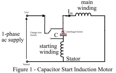
Sorry I made a balls up with the picture, the edit went off and I couldn't delete it. Any way back to the correct picture.
The centrifugal switch remains closed until the motor is about 75% up to speed, then it opens disconnecting the start winding. In reality it doesn't matter which side of the capacitor it is connected to. I've just seen that the labels on the windings should be swapped, though in practice both windings are probably similar.
Sorry I made a balls up with the picture, the edit went off and I couldn't delete it. Any way back to the correct picture.
The centrifugal switch remains closed until the motor is about 75% up to speed, then it opens disconnecting the start winding. In reality it doesn't matter which side of the capacitor it is connected to. I've just seen that the labels on the windings should be swapped, though in practice both windings are probably similar.
Elektrishun
Ultra Member
Capacitors for AC motors are not polarized.Does this mean it's polarized and this is a nonstarter or could it be replaced?
View attachment 85995
Be careful when handling or testing a capacitor. The capacitor can store a charge. You should "short" the terminals before touching or connecting to a meter. Some people use a screwdriver with an insulated handle (plastic, rubber, etc).

Not to worry see the new picture. The wiring remains the same but the centrifugal switch is placed where the red "X" is.
I have to be honest. Your method hurts my brain. I don't even think it's right. But it might be. I just think it's too hard to see the simplicity of what should really be happening.
A few comments.
Most single phase motors will just sit there and buzz when connected to power. But you can get them spinning by grabbing the output shaft and giving it a "kick". After that it will spin up and continue to turn in whatever direction you kicked it.
Even though you could, nobody wants to have to kick start their motor spinning in the desired direction all the time.
So, motor designers came up with this idea of kick starting the motor with a start winding instead. The direction and polarity of the start winding is what determines which way the motor starts, not the capacitor. The purpose of the capacitor is to create a phase shift in the winding fields of the start winding vs the main winding. It is this phase shift between the forces of the two fields that gives it the magnetic force difference it needs to start spinning. Without the phase shift both windings would generate a field at the same time no matter which way they are wired. They would both just sit there and buzz. The two magnetic fields need a time difference (phase difference) to generate a force difference to get the motor going.
Reversing the capacitor does nothing to change the phase shift. It will be the exactly the same either way. Instead, you need to reverse the wiring of the start winding so it is on the other side of the main winding by whatever amount of phase shift the capacitor generates.
The start winding sets the direction, and the capacitor creates the phase change needed to get that direction going.
The purpose of the centrifugal switch is to disable both the start winding and the capacitor once the motor starts turning on its own.
Here is a simple drawing of the correct way to reverse the direction of a single phase motor. This drawing makes it more obvious that it's the start winding that you are reversing, not the capacitor.
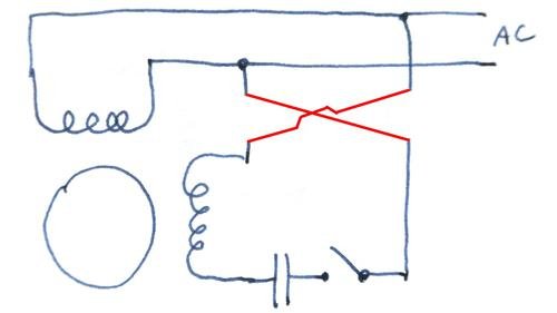
If you want to test my explanation, go ahead and just reverse the capacitor leads. You won't hurt it, but it will change nothing.
You could also draw this with just the start winding reversed and it would work just fine. But in the real world thats harder to do because the centrifugal switch is buried inside the motor. It's just easier to draw it with the entire start circuit reversed because those wires are usually accessible.
Elektrishun
Ultra Member
@Garzweiler
The motor that you are currently working on, is it the one pictured in post #12?
Second question - you said the motors you have run smooth. I am assuming that includes the motor in post #12?
The motor that you are currently working on, is it the one pictured in post #12?
Second question - you said the motors you have run smooth. I am assuming that includes the motor in post #12?

Garzweiler
Active Member
@Garzweiler
The motor that you are currently working on, is it the one pictured in post #12?
Second question - you said the motors you have run smooth. I am assuming that includes the motor in post #12?
Yes, the one in #12 is also pictured in post #19.
Garzweiler
Active Member
So the idea is to have the lines to the start coil flippable and leave the run alone?I have to be honest. Your method hurts my brain. I don't even think it's right. But it might be. I just think it's too hard to see the simplicity of what should really be happening.
A few comments.
Most single phase motors will just sit there and buzz when connected to power. But you can get them spinning by grabbing the output shaft and giving it a "kick". After that it will spin up and continue to turn in whatever direction you kicked it.
Even though you could, nobody wants to have to kick start their motor spinning in the desired direction all the time.
So, motor designers came up with this idea of kick starting the motor with a start winding instead. The direction and polarity of the start winding is what determines which way the motor starts, not the capacitor. The purpose of the capacitor is to create a phase shift in the winding fields of the start winding vs the main winding. It is this phase shift between the forces of the two fields that gives it the magnetic force difference it needs to start spinning. Without the phase shift both windings would generate a field at the same time no matter which way they are wired. They would both just sit there and buzz. The two magnetic fields need a time difference (phase difference) to generate a force difference to get the motor going.
Reversing the capacitor does nothing to change the phase shift. It will be the exactly the same either way. Instead, you need to reverse the wiring of the start winding so it is on the other side of the main winding by whatever amount of phase shift the capacitor generates.
The start winding sets the direction, and the capacitor creates the phase change needed to get that direction going.
The purpose of the centrifugal switch is to disable both the start winding and the capacitor once the motor starts turning on its own.
Here is a simple drawing of the correct way to reverse the direction of a single phase motor. This drawing makes it more obvious that it's the start winding that you are reversing, not the capacitor.
View attachment 85999
If you want to test my explanation, go ahead and just reverse the capacitor leads. You won't hurt it, but it will change nothing.
You could also draw this with just the start winding reversed and it would work just fine. But in the real world thats harder to do because the centrifugal switch is buried inside the motor. It's just easier to draw it with the entire start circuit reversed because those wires are usually accessible.
Elektrishun
Ultra Member
So, with the way it was originally wired in post #12 the motor would run just fine?Yes, the one in #12 is also pictured in post #19.
If true, that suspect wire that was pointed out in #15 is likely a jumper where an external "ON/OFF" switch on the motor houseing could have been connected. The jumper makes those 2 terminals common. With the jumper in place you can view it as one terminal instead of two.
Sorry to back track but since that is the motor you are working with currently I am curious about that detail and whether it got sorted out.
So the idea is to have the lines to the start coil flippable and leave the run alone?
Yes. Exactly.
You just need to keep in mind that it is easier to flip the start coil, the cap, and the centrifugal switch altogether as though they were just one circuit. The, reason for this is that the centrifugal switch is buried down inside the motor and you can't get at the wire between it and the start winding.
Garzweiler
Active Member
Success! Sort of!
I have wired the changeover in correctly and can now reverse the motor's direction - but it doesn't sound as happy going one way as the other. I'm not sure if that's a design thing or if I need to reinspect my reassembly.
I have wired the changeover in correctly and can now reverse the motor's direction - but it doesn't sound as happy going one way as the other. I'm not sure if that's a design thing or if I need to reinspect my reassembly.

someidiot
Well-Known Dismemberer
scribd is awful. You're supposed to be able to upload stuff to earn download credits, but the last time I did that they accepted all the uploads and the credits never appeared, so I'm done with them. I'll be happy to upload the book linked to in post #31 here, but I don't know whether the forum will permit a 32M PDF.
scribd is awful. You're supposed to be able to upload stuff to earn download credits, but the last time I did that they accepted all the uploads and the credits never appeared, so I'm done with them. I'll be happy to upload the book linked to in post #31 here, but I don't know whether the forum will permit a 32M PDF.
Send a PM to @BaronJ. He might be able to email you a copy.
I share your view of Scribd. I spent hours a few years ago trying to upload a document only to get a totally useless credit I could do nothing with.
Elektrishun
Ultra Member
Success! Sort of!
I have wired the changeover in correctly and can now reverse the motor's direction - but it doesn't sound as happy going one way as the other. I'm not sure if that's a design thing or if I need to reinspect my reassembly.
Bearings? Running one direction for years and there's a wear pattern???
but it doesn't sound as happy going one way as the other.
I agree with @Elektrishun.
But I'd like to add another possibility. Once you get it going, the start wiring doesn't matter anymore. So if it starts properly in both directions, your wiring is fine. But it could be that the centrifugal switch isn't disengaging the start winding after it gets going. That would make the start winding fight the run winding a bit. When you turn it off, listen for the centrifugal switch to re-engage. If that doesn't happen, then likely it never turned off and that's your problem.
Garzweiler
Active Member
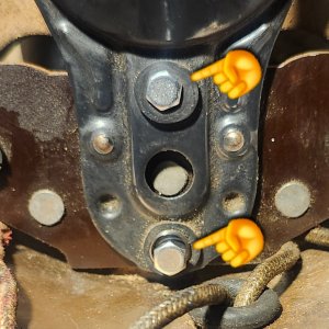
Okay, I think the issue may be some more problems with this centrifugal switch. There are two screws holding it in place, one with a spring which creates the pivoting action. I am not certain how it ought to be tensioned/adjusted but right now I think it's loose and rattling.
Attachments
BaronJ
Ultra Member
Hi Garzwieler,So the idea is to have the lines to the start coil flippable and leave the run alone?
It doesn't matter swapping the wires on either winding will have the same effect on direction. Its just that getting at the right pair can be awkward.
Centrifugal switches can be a pain in the proverbial !
BaronJ
Ultra Member
We Need Pictures !Success! Sort of!
I have wired the changeover in correctly and can now reverse the motor's direction - but it doesn't sound as happy going one way as the other. I'm not sure if that's a design thing or if I need to reinspect my reassembly.
It could be that the centrifugal switch is wired in the opposite end of the winding.
Last edited:
We Need Pictures !
It could be that the centrifugal switch is wired in the opposite end of the winding.
I don't think that should matter.
@Garzweiler - The question is, is it releasing? It's not hard for me to imagine one that releases in one direction but not in the other. If you can't fix it, it may need to be replaced. Good luck with that one........
I asked earlier if you can hear the click when it re-engages on spin down. This is an important question.
Garzweiler
Active Member
I hooked up my multimeter to the switch and it's definitely a problem. It releases intermittently in one direction now and not at all in the other. I've cleaned and polished as much as I can but there still seems to be something not quite right about how the centrifugal switch is set.I don't think that should matter.
@Garzweiler - The question is, is it releasing? It's not hard for me to imagine one that releases in one direction but not in the other. If you can't fix it, it may need to be replaced. Good luck with that one........
I asked earlier if you can hear the click when it re-engages on spin down. This is an important question.