• Scam Alert. Members are reminded to NOT send money to buy anything. Don't buy things remote and have it shipped - go get it yourself, pay in person, and take your equipment with you. Scammers have burned people on this forum. Urgency, secrecy, excuses, selling for friend, newish members, FUD, are RED FLAGS. A video conference call is not adequate assurance. Face to face interactions are required. Please report suspicions to the forum admins. Stay Safe - anyone can get scammed.

ELS installation questions

Oh and here's a photo of the TI based development board made by Spectrum Digital. Basic Development Software was free but the programmer was $200 or so IIRC. I built the add on board for my CANRF and general playing around with DC motors because back in 2003 Servo Motors were horrendously expensive and Princess Auto was selling cheap surplus treadmill motors. A Gecko Stepper Motor driver was more than $100 US and the Stepper motors were all in the $80 and up range. I had the idea that I would design and build a DC Servo Motor drive too.

So prices have come way down at a cost though.

F2812Brd1.jpg

I built this and took a trip down to Anaheim for a seminar on how to work with it.

tstbrd1.webp
 

Attachments

And here's the biggest down side to my ELS and it's a biggy. You CANNOT change the spindle speed once you have started threading. You must complete the threading operation at the same spindle speed setting. Turning doesn't matter. Threading does.

Because unlike turning, threading must be both indexed and syncronized? If you change speeds, you can maintain index but because you use a 1 PPR encoder you cannot maintain sync unless you resync.

If my guess is right, it's sort of analogous to picking up an existing thread.

Sorry, I love to guess at such things!
It wasn't until I dug into LinuxCNC and their trajectory planner that I finally understood better what the issue is and why it's hard to solve on a small 8 bit micro-processor.

Recall from simple physics Distance d = 1/2 * a * t^2 and Velocity v = d/t. Acceleration is change in velocity over change in time.

On my ELS the acceleration is a fixed value that gets the motor up to target velocity as quickly as possible without stalling.

What velocity? The velocity required to for the threading or turning ratio. So in the case of turning lead screw pitch threads the lead screw turns at the same speed as the spindle. ie. One revolution of the spindle results in one revolution of the lead screw and if the pitch is 10 TPI it's moved 0.1". That's what gears do too. If the spindle is turning 600 RPM then so is the lead screw.

Acceleration isn't an issue because the half nut is engaged at the mark so the nut enters the lead screw so the tool enters the cut at the right spot. But with my ELS we start from a stop so first we have to accelerate up to velocity. The distance travelled varies depending on the velocity. That means the distance the spindle rotates varies depending on the target velocity.

If we double the spindle speed it takes half the time to turn the same distance but our lead screw still requires the same time as before so by the time it reaches the spindle speed the spindle has travelled much further.

The ELS/MACH3/LinuxCNC uses the spindle index pulse to register where the thread starts based on the velocity and the trajectory to reach that velocity. LinuxCNC will adjust the acceleration so the distance travelled when it's up to speed is exactly the same distance from the index pulse. And it adjusts that based on the encoder AB signals to track that spindle velocity.

Or to say it differently. The goal is to move the carriage from a starting position to a target position so it reaches that at the same point as the spindle as turned from the index pulse. LinuxCNC has the computational capability to track and adjust acceleration and speed so the target position and velocity is met and then it remains at that setting tracking the spindle velocity.

My ELS can't adjust the acceleration on the fly so that the distance the spindle rotated matches the distance the lead screw turned. Since AC motors on lathe are synchronized to the line frequency and are extremely stable for the light load of threading we know it always moves the same distance around from the index pulse at a fixed RPM. The acceleration up to that speed for the carriage lead screw is also fixed so once it reaches that velocity it's also at the same physical spot from the head stock every single time. So the tool enters the previous thread perfectly.

Many of the older lathes didn't have or were missing their threading dials and multiple gears. Encoders were running more than $200 without expensive belts and pulleys back in 2005. The 3D printing didn't exist so making your own pulleys and slotted disks were difficult. A 1 PPR solution worked for both MACH2/3 and my ELS.

Now you can buy a BeagleBone Black and run MachineKit and have full CNC for under $100.
 
My ELS can't adjust the acceleration on the fly so that the distance the spindle rotated matches the distance the lead screw turned.

The explanation is fascinating, and not quite what I expected, but it's still a synchronization problem! LOL!

Car engines had the same problem initially when engineers didn't understand that counting clock cycles wasn't a great proxy for physical position (unlike a hardware cam) until we went to proximity sensors on the ring gear to sense each gear tooth and faster processing so the control system knew exactly how much the speed was changing (accelerating) even continuously within a single revolution.

Although I don't want ELS, I do want better resolution for rpm. Hence my interest in multiple sensors instead of just one. But after I get what I want, I might not like it! LOL!
 
It's even a synchronization problem on a manual lathe. Engage the half nut on the wrong line or the wrong number when threading and you get a trashed thread. Or for metric, leave nut engaged and turn off spindle at end of cut while simultaneously removing tool using cross slide. Then switch into reverse until far enough past the start of the thread thread so it's up to cutting speed when it hits the work. Stop spindle, turn cross slide back to 0. Move compound in a bit more and turn on spindle to forward. Rinse and repeat.

Heaven help you if you accidentally disengage the half nut for that metric thread. It can take a while to get it properly lined up again.

We used a couple of crank sensors on this engine to control both ignition and multi-port sequential fuel injection just counting time between sensors. We did not find significant issues using that approach when testing on the dyno. What we did have to do, after an engine failure and glide back to the airport for a dead stick landing was ensure that all the A/D reading of sensors was not done during any of the time that either injectors or CD ignition was in process. The Ignition caused the most noise and corrupted the mixture reading to momentarily cause an over rich mixture to stall the engine. Never happened on the dyno. Happened in the air. The engine would have restarted immediately but it was fluky.
The Honda VTEC engines were also used for Hovercraft.
 
In the past, when anyone wanted an ELS for their lathe mine was the only one available. Now mine isn't even mentioned. I guess if I want more visibility I have to do a better video than this one.
For mine you need a 9-12V power supply, a box to put it in and a one pulse per rev sensor. The rest is the same with respect to motors and drives for the axis. Mine can run with only the Z axis although if you want tapering you need both.
I have a taper attachment on my South Bend so I've never been motivated to power the cross slide.
What I can say is that over the years I've done metric threads, imperial threads, multi-start threads but mostly it's just nice to use a keypad to key in BEGIN and END positions or move to where I want to be and select BEGIN or END on the keypad.
Yes there is a rotary know (MPG) but it's used to move the axis. Not to select digits or parameters I have arrow keys for that.
GrumbleMode := ON;
The day I will fall in love with a rotary knob to select parameters is when I see microwave ovens at Walmart use that for setting and controlling the microwave or stove.
Recall too we went from sending texts using a telephone keypad and hitting a number key several times to select letters. Rotary knobs for that sort of selection is only done on the Electronic gearing systems because the difficulty in creating a 35 button keyboard. Doesn't come as commercial off the shelf from the far east so it isn't done.
GrumbleMode := OFF;

Anyway I've sold my ELS kits all over the world including even Tasmania, South Africa, Europe and never one returned. So since no one on this thread mentioned mine I thought I would.
Thanks for adding that link. Do you have a website for more information? I am still in the research mode and haven't decided on one specific unit yet so I would like to learn more about what you have to offer. I am realizing that I will need to become comfortable with some electronic assembly work. I don't really have any experience with this finesse-y type soldering and understanding how this type of thing all goes together (spent my career as a finish carpenter), but I enjoy learning new things.
 
Thanks for adding that link. Do you have a website for more information? I am still in the research mode and haven't decided on one specific unit yet so I would like to learn more about what you have to offer. I am realizing that I will need to become comfortable with some electronic assembly work. I don't really have any experience with this finesse-y type soldering and understanding how this type of thing all goes together (spent my career as a finish carpenter), but I enjoy learning new things.
It started as a Yahoo group in 2005 and then moved to groups.io. https://groups.io/g/E-Leadscrew
Sign up and there are all sorts of pictures documents. A bit overwhelming of course because the messages and discussions go back so far.
You can also post questions and just ask. We have a fundamental rule there is no such thing as a dumb question. People who might respond in a negative manner are immediately placed into edit mode where their postings are checked before they go on. Like this forum we don't allow politics or insults etc.
There's been a whole thread just recently on the Rocketronics. The group was set up for Electronic Lead Screws because the CNC groups were quite disparaging about the idea of an ELS. So we formed a separate group. I just happened to be the one who made a full featured unit. But as long as discussions on other electronic units don't turn into insults then all is fair.

As a finish carpenter you'll have no trouble building a box. Other than that the only detailed work is the spindle sensor. With a cheap break out board you can set it up so you could run CNC instead.

There are lots of people who will help. Here or on the forum.
Thanks John. I will go and do some reading. As you probably have realized I am not familiar with electronics and have never really had the need to learn (till now...).

I agree wholeheartedly about the wealth of knowledge on this forum and everyone's willingness to help a guy out. I appreciate your comment about no question being dumb. Over the years I have taught many youngsters the world of carpentry and always tried to be approachable and make sure no one felt they couldn't ask a question. On several occasions they taught me a different way of doing something that made sense so I have always felt you have be "teachable" even if its something you felt you had mastered.
And just to clear up any misconceptions about this. The E-Leadscrew group was formed because there weren't any solutions. We discussed at length how to build one and what features it should have. Even then a few of the CNC group joined and were still hammering on the idea that it was a pointless exercise. All you need are a couple of buttons and a knob along with an LCD screen. That user even went as far as to build one like that. I think his was the only one built.

A friend of mine was going to buy one of my ELS units. He wired up the motors and a Break Out Board and then, since he had MACH running on his mill tried it on the lathe. He never did buy an ELS. Loves his CNC. And that's the whole point. What ever works for you is what makes me happy. I will tell you what I don't like about mine and what it can't do. Unfortunately some of the Arduino based Electronic Gearing developers are vague or don't mention or belittle something that mine can do and theirs can't. That's the type of attitude we also got from the CNC community.

So do your research. Lots of people here or on the E-Leadscrew group will help with electronics questions etc.
 
Thanks John. I will go and do some reading. As you probably have realized I am not familiar with electronics and have never really had the need to learn (till now...).

I agree wholeheartedly about the wealth of knowledge on this forum and everyone's willingness to help a guy out. I appreciate your comment about no question being dumb. Over the years I have taught many youngsters the world of carpentry and always tried to be approachable and make sure no one felt they couldn't ask a question. On several occasions they taught me a different way of doing something that made sense so I have always felt you have be "teachable" even if its something you felt you had mastered.
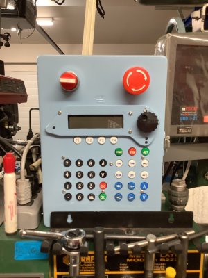
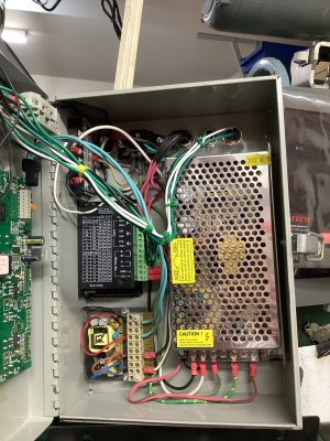
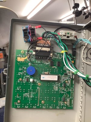
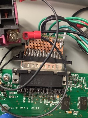
It’s possible to build John‘s ELS with zero soldering. Here’s my installation. I soldered the cables for external connections to the stepper and spindle sensor, but these could have easily be done with screw terminal connectors. The most complicated connector is a DB25 connector off the main board, and even though I used a soldered one, a screw terminal version is available off the shelf.
 

Attachments

  • IMG_6500.jpeg
    IMG_6500.jpeg
    404.3 KB · Views: 13
  • IMG_6501.jpeg
    IMG_6501.jpeg
    619.2 KB · Views: 11
  • IMG_6502.jpeg
    IMG_6502.jpeg
    537.2 KB · Views: 10
  • IMG_6503.jpeg
    IMG_6503.jpeg
    580.5 KB · Views: 11
It’s possible to build John‘s ELS with zero soldering. Here’s my installation. I soldered the cables for external connections to the stepper and spindle sensor, but these could have easily be done with screw terminal connectors. The most complicated connector is a DB25 connector off the main board, and even though I used a soldered one, a screw terminal version is available off the shelf.
That looks tidy.
What lathe is this running?
 
Back
Top