• Spring 2024 meetup in Calgary - date Saturday, April 20/2024. discussion Please RSVP Here to confirm and get your invitation and the location details. RSVP NOW so organizers can plan to get sufficient food etc. One week to go! More info and agenda
  • We are having email/registration problems again. Diagnosis is underway. New users sorry if you are having trouble getting registered. We are exploring different options to get registered. Contact the forum via another member or on facebook if you're stuck. Update -> we think it is fixed. Let us know if not.
  • Spring meet up in Ontario, April 6/2024. NEW LOCATION See Post #31 Discussion AND THE NEW LOCATION

ELS Electronic Lead Screw Concept

Susquatch

Ultra Member
Administrator
Moderator
Premium Member
Pretty well everyone who adds an electronic drive to their lathe will do it only to the lead screw regardless of Electronic Gearing, ELS or CNC.

I get all that John. Yes, it's an option to go that way.

But my half nut is only designed to handle threading. If I started to use it for feed too, it would be toast in no time. My lathe is a 14x40. Not big, but not small either. The feed and threading operations are separated for a reason.
 

Susquatch

Ultra Member
Administrator
Moderator
Premium Member
Do you mean variable speed control that would allow speed control of the spindle independent of the carriage feed? That can't be done with just a vfd?

I wish.....

But no, I just mean variable speed of motor input to Lathe. That meaning spindle, feed, and threading are all dependent on motor input speed and only as independent as allowed by available gearing. Nothing more than that.

My primary goal is slower spindle speeds than my factory lowest speed of 70rpm.

But it should also be possible to increase spindle speed manually as diameter goes down during parting or facing operations. Of course, that will also increase feed rate. Prolly a good balance in there someplace.
 

PaulL

Technologist at Large
Premium Member
My setup rides at the headstock and the servo drives the gearbox that distributes power to either the lead screw or the drive shaft. So I select with the old lever if I'm feeding vs threading, and the E-gears (Clough42's one, basically) selects a different servo speed for each one.
I do still have to select thread/feed on my e-gears panel *and* at the lever.
If I ever pull my gear box apart I'll add a sensor on the feed/threading lever to automate that part of the control panel.
 

jcdammeyer

John
Premium Member
Do you mean variable speed control that would allow speed control of the spindle independent of the carriage feed? That can't be done with just a vfd?
Yes. I don't think that's the underlying question though although perhaps I'm overthinking it.
I've been working on a code upgrade for my ELS that let's it put out a PWM pulse rate on DB25-1 compatible with that little MACH3 Cheap Chinese BoB.

The software is far enough along that the some of the buttons on the keypad serve as Spindle ON and Spindle Speed but as yet don't produce an output.

My ELS can already report SFM. Set the X value to the radius and select SFM instead of RPM and it reports the surface speed. Now as you move outwards of course the SFM increases because more material passes by the tip at the same RPM. But my ELS is designed to always start cutting at X=0.000.

Like setting the dial at 0.000 and running a pass, measuring diameter and then deciding 0.005 needs to come off. Easier to then move in 0.005" from zero and reset it to zero than to remember that it's at -0.017 from other passes and we have to in our head add -.005 which is then -0.022. And remember if we want to do a spring pass to back it out, and return it to ... what was that again... oh yeah -0.0023. oops.. Now it's 0.002" under size. Returning to the 0.000" set point is human factors design. Our brains work better that way.

To achieve and ideal surface finish the point is to maintain a set surface speed by varying the RPM while facing off at a specific pitch if you will. To do that one needs to control the spindle speed and have a facing off from BEGIN to END along with a distance per rev. So you have to calibrate the tool tip so you know where it is relative to the spindle center line. That introduces a whole new element of CNC like operations.

Although the infrastructure is in place in my ELS I've never done it (nor been pushed to do it) because although my South Bend VFD can accept 0-10V I don't have a powered cross feed on it (at least not directly).

My Gingery has powered cross feed but I don't have a variable speed spindle. So hard to test something.

Anyway, most people if they want to go that far just put CNC on their lathe, learn the bits needed and can do way more.
 

whydontu

I Tried, It Broke
Premium Member
Up and running. Bezel made from dollar store nylon cutting board, cut on my 3018 CNC router. Didn't think how ugly the cutting board surface is, looks like crap but I'm too lazy to replace it right now.

Buttons engraved on ancient Hermes pantograph, might re-do them as well. My first try to get accurate alignment, maybe 80% successfull.


Boot Screen.jpg

Running.jpg
 

TorontoBuilder

Ultra Member
Up and running. Bezel made from dollar store nylon cutting board, cut on my 3018 CNC router. Didn't think how ugly the cutting board surface is, looks like crap but I'm too lazy to replace it right now.

Buttons engraved on ancient Hermes pantograph, might re-do them as well. My first try to get accurate alignment, maybe 80% successfull.


View attachment 32716

View attachment 32717
so did the gluing of your mylar film not work out okay, or you just decided such buttons would look better?
 

whydontu

I Tried, It Broke
Premium Member
so did the gluing of your mylar film not work out okay, or you just decided such buttons would look better?
Gluing the Mylar worked <ok>, but I couldn’t get the edges to tuck down tight to the metal chassis, and I thought it would just annoy me if it peeled off. I found a STP file for a bezel on @jcdammeyer ‘s ELS website https://groups.io/g/E-Leadscrew and one of the group members was kind enough to modify the STP file to fit my needs.

So I removed the Mylar, sanded and painted the chassis and went this route.
 

TorontoBuilder

Ultra Member
Gluing the Mylar worked <ok>, but I couldn’t get the edges to tuck down tight to the metal chassis, and I thought it would just annoy me if it peeled off. I found a STP file for a bezel on @jcdammeyer ‘s ELS website https://groups.io/g/E-Leadscrew and one of the group members was kind enough to modify the STP file to fit my needs.

So I removed the Mylar, sanded and painted the chassis and went this route.
Yeah I find mylar requires multipart/step adhesives for bonding. Or heat sealing. I'm not sure how I'll do this step
 

jcdammeyer

John
Premium Member
Yeah I find mylar requires multipart/step adhesives for bonding. Or heat sealing. I'm not sure how I'll do this step
The original box has a slight recess resulting in a ridge along the top and bottom edges. And the sides slope up and away. So it's hard to catch the edge of the mylar overlay. I'm pretty sure I used spray glue almost 15 years ago. And I've had to clean it a number of times to get the gunge off from WD-40 or other oils and greasy fingers.

Some have just fastened a trim frame around the edge to prevent it from catching on things. But if you have a larger or thicker panel just using a face mill to create a recess when you are making the holes will work too.

OlderOverlay.jpg
 

kevin.decelles

Jack of all trades -- Master of none
Premium Member
Take me through the buttons —where did you source the coloured pieces? Picture of your pantograph !
 

whydontu

I Tried, It Broke
Premium Member
Take me through the buttons —where did you source the coloured pieces? Picture of your pantograph !
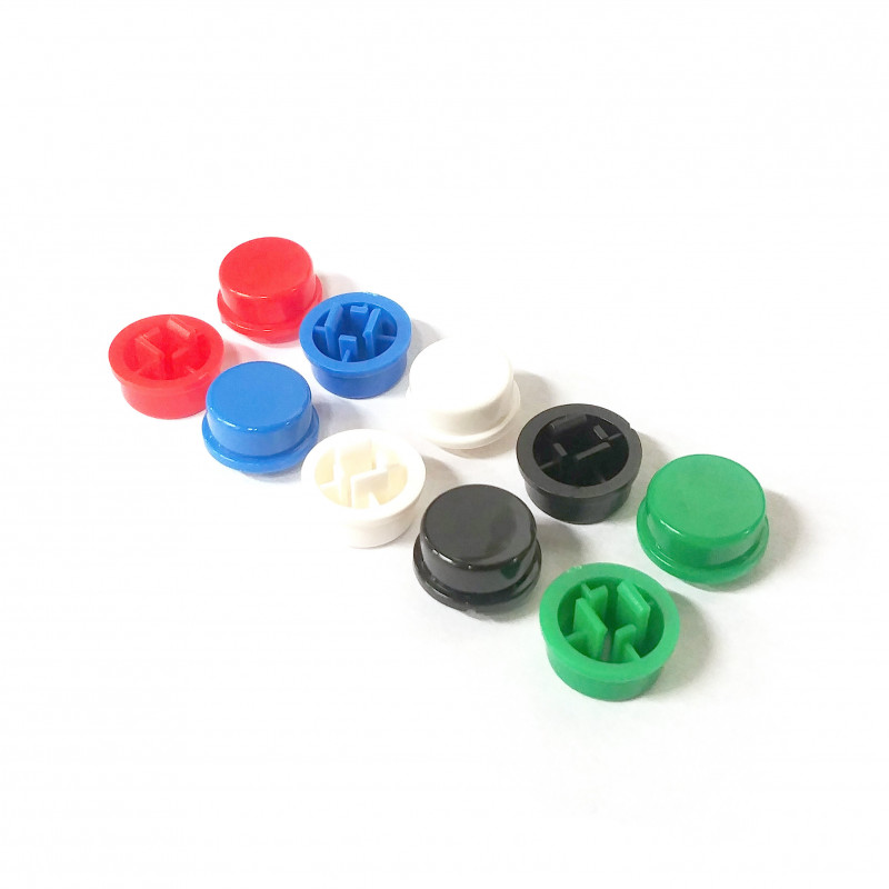
@jcdammeyer was nice enough to design a unit using very common parts. Switches are standard 12x12x7.3 tactile switches, use these caps. I bought from Lee's Electronics in Vancouver, also ordered a slew of them off eBay:


tactile-switch-omron-b3f-cap-replacement-5-colours-10pcs.jpg

Engraver is a New Hermes TX I bought a few months ago for $400, including a few thousand font tiles. You can pick them up for a song, I've seen them as low as $100 since old-style manual engraving is defunct and replaced with laser machines. Mine came from a shop that does key cutting, they used to use this to engrave mugs and touristy stuff.

Getting one of these is like the old, old days when you got a Dymo labeler - two weeks after getting a labeler, everything in your house had a label. Many, many things in my shop are now engraved.

All I had to do was make us a simple jig to hold the caps, and away I went. Engraved and then filled in with paint markers, let it dry, and filed off the excess.


New Hermes TX Engraver.jpg

Paint.jpg
 
Last edited:

jcdammeyer

John
Premium Member
Nice machine. Interesting seeing carpet in your wood shop area.

The difference between the buttons you bought and the thousands I have in stock is that yours have flat tops while mine are slightly domed. At some point (project #42) I had planned to use my CNC router to engrave the button tops which meant I had to be able to follow the domed profile. I even bought the engraving tool bits.

But nothing happened after that. And yes. Standard buttons on my ELS. Not only that instead of through hole there are pads there for surface mount versions but those buttons were more expensive and the cost for installing them on the opposite side of the boards with pick and place was also more expensive. My ELS kit was always designed to be cheaper than anything you could buy ready to go.

And it was until China showed up with $2 Arduinos which cost less than the processor on my ELS.
 
Top