I’m starting down the path of adding an ELS to my Busy Bee B2227L lathe.
Background:
I really like the convenience of the gearhead configuration of the B2227L, but I’d kill for a quick-change feed box.
I rarely thread anything on the lathe, in 10 years I’ve maybe cut single-point threads three times. Usually I just use dies and hand-thread.
I often machine long shafts or piping, so I use power feed a lot. But changing gears to switch from roughing to finish feed is a pain.
I want to come up with a reasonable way to change feed rates. I have no intention of going full CNC.
So:
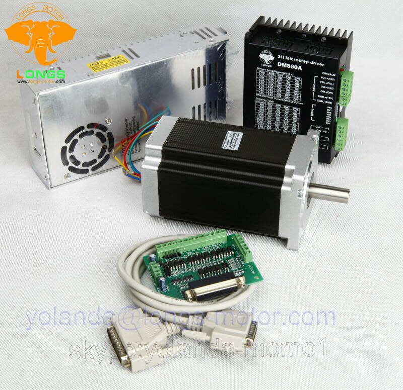
I’ve ordered a NEMA34 1600in-oz motor and driver controller, and intend to combine it with one of these:
https://create.arduino.cc/projecthub/nsr5058/lathe-electronic-lead-screw-52a9c5
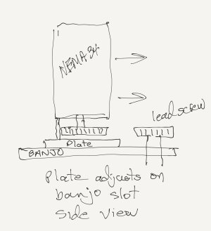
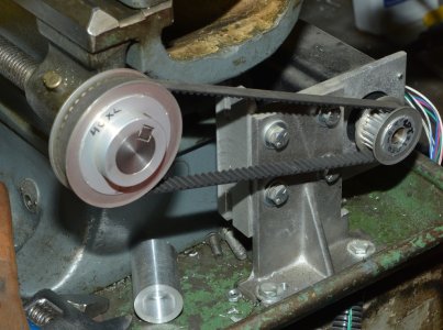
Instead of using a toothed belt, I plan to mount the stepper on a plate that will slide along the existing change gear banjo, and make an adapter to mount a change gear on the stepper motor shaft. Direct gear to gear, no belt. This also means I can in effect change the goofy BB 7 TPI leadscrew to 10 TPI by using a 35/50 or 70/100 gear set. Or any other ratio, if it turns out I need to adjust stepper speed in relation to spindle speed.
Basically, I’ll replace items 5, 6, 11, 23, and 24 with the stepper. Mounted to a plate that slides along the adjustment slot in #7.

Questions:
NEMA34 too big?
Any reason the gear-to-gear concept is bad?
Suggestions from you folks who have done this type of hack?
Thanks
Background:
I really like the convenience of the gearhead configuration of the B2227L, but I’d kill for a quick-change feed box.
I rarely thread anything on the lathe, in 10 years I’ve maybe cut single-point threads three times. Usually I just use dies and hand-thread.
I often machine long shafts or piping, so I use power feed a lot. But changing gears to switch from roughing to finish feed is a pain.
I want to come up with a reasonable way to change feed rates. I have no intention of going full CNC.
So:
I’ve ordered a NEMA34 1600in-oz motor and driver controller, and intend to combine it with one of these:
https://create.arduino.cc/projecthub/nsr5058/lathe-electronic-lead-screw-52a9c5
Instead of using a toothed belt, I plan to mount the stepper on a plate that will slide along the existing change gear banjo, and make an adapter to mount a change gear on the stepper motor shaft. Direct gear to gear, no belt. This also means I can in effect change the goofy BB 7 TPI leadscrew to 10 TPI by using a 35/50 or 70/100 gear set. Or any other ratio, if it turns out I need to adjust stepper speed in relation to spindle speed.
Basically, I’ll replace items 5, 6, 11, 23, and 24 with the stepper. Mounted to a plate that slides along the adjustment slot in #7.
Questions:
NEMA34 too big?
Any reason the gear-to-gear concept is bad?
Suggestions from you folks who have done this type of hack?
Thanks