• Scam Alert. Members are reminded to NOT send money to buy anything. Don't buy things remote and have it shipped - go get it yourself, pay in person, and take your equipment with you. Scammers have burned people on this forum. Urgency, secrecy, excuses, selling for friend, newish members, FUD, are RED FLAGS. A video conference call is not adequate assurance. Face to face interactions are required. Please report suspicions to the forum admins. Stay Safe - anyone can get scammed.

ELS Electronic Lead Screw Concept

Here is the big difference between steppers and servo (depending on which you get). Steppers torque rating is holding force which is different for moving force, which is why you generally size up on steppers.

I'll direct you the Clearpath SDSK servo. Takes input like a steppers with all of the benefits of a servo. There torque rating is running torque with momentary peak being a lot higher. I have NEMA 34 with torque around 230in-oz full rpm 100% duty cycle, 10% at about 200rpm is in excess if 1000in-oz. They also have an internal count for positioning. BTW SDSK stands for Step Direction (input like a stepper) Stepper Killer ;). They are smooth and quiet compared to steppers.

Forgot to add they come in two flavours 800counts per rev or 6400 counts per rev.
 
Last edited:
The reasons the Ardunios work as electronic gearing has nothing to do with arduino and everything to do with the Atmel processor. The one used in the Arduino can set up more than one pin to interrupt the processor.

The problem with a forum exchange like this is that neither of us knows what the other knows. We might have a great Venn overlap of knowledge or we might have none. I think we have a lot more overlap than you are assuming. But that's ok. Better to assume less than too much.

Perhaps you recall that I wrote hardware drivers and control software back in the early days and designed automotive control systems after that. One cannot do that without fully understanding timers, counters, and Interrupts.

Perhaps you will also remember my questions about writing code outside of the Arduino compiler that would integrate Arduino code with my own microcontroller machine code to directly access the Interrupts and timers and counters of the atmel microcontroller. I know that's not the best way to do things but it was an area of interest for me because of my previous success with hardware control doing things like that.

Anyway, if I wanted to do my own ELS, that would be one thing. I don't plan to do that right now. I probably won't ever do that myself. I'm actually quite happy with a fully manual lathe and changing gears when I thread.

Right now, I'm just enjoying the discussion around what @whydontu wants to do. He is not planning any threading at this time. He just wants feed control.

My own longer term plans don't really include a lot of machine tool control. I'm just using that for now as a learning platform to serve my real microcontroller interests. As a farmer, I have a keen interest in precision planting control for row crops. Equipment like that exists, but it is prohibitively expensive at the scale of my farm operations. Once I get to the point of designing hardware I'll be looking for all the help I can get.
@Susquatch In no way was I trying to insult your experience. I'm sure others are reading this thread with way less experience than yours. So I tried to keep things simple. So my apologies if I somehow came across as arrogant or insulting. Wasn't meant that way.
 
@Susquatch In no way was I trying to insult your experience. I'm sure others are reading this thread with way less experience than yours. So I tried to keep things simple. So my apologies if I somehow came across as arrogant or insulting. Wasn't meant that way.

Too funny! That wasn't my intent either. I honestly thought you were just trying to teach me something and I was just saying it isn't necessary!

But you are also right. I need to remember I'm not the only one reading this thread!

It's all good! No offense was taken at all!

Carry on!
 
Here is the big difference between steppers and servo (depending on which you get). Steppers torque rating is holding force which is different for moving force, which is why you generally size up on steppers.

I'll direct you the Clearpath SDSK servo. Takes input like a steppers with all of the benefits of a servo. There torque rating is running torque with momentary peak being a lot higher. I have NEMA 34 with torque around 230in-oz full rpm 100% duty cycle, 10% at about 200rpm is in excess if 1000in-oz. They also have an internal count for positioning. BTW SDSK stands for Step Direction (input like a stepper) Stepper Killer ;). They are smooth and quiet compared to steppers.

Forgot to add they come in two flavours 800counts per rev or 6400 counts per rev.
I'd argue that step servo units aren't really any different other than throwing different numbers around. Physically you can't generate more torque with a give size step motor regardless of the control method.

I'll refer back to the amp x turns = torque. For 3A through a stepper motor winding that has N turns you will get a torque value based on the size of the magnet assembly on the armature and the distance away from the armature center line. The exact details aren't important and at this point in my life way over my head.

Say for example you look at this motor:
with this torque curve.

3A per phase and 282 oz-in torque and @Degen is correct that it's the holding torque. That's about 1.46 ft-lbs or 1.46 lbs hung on a 1 foot long arm attached to the motor shaft. Likely if you try to turn the motor it may step a bit but not much.
Really this motor is more like a 140 oz-in motor up to 600 RPM with 8 micro steps/step. That's what the torque curve shows.

As I mentioned before micro-stepping open loop isn't all that useful for exact positioning so it will run 600 RPM with a 14 oz-in load but when you stop it may not be exactly where you want (to the micro-step). This is where the closed loop motors excel. They will continue to adjust the current through the windings to get to the target position. They may even apply more than the rated current to force the move if the load is too high but there are problems with that including extra heat and potential demagnetizing the rotor.

A motor that is constantly lagging due to too high a load, and requires extra current to keep it from losing position then isn't being used to spec. For a commercial project we did try the step-servos. Ended up going to brushless DC servos which were also much quieter.
 
Forest for the trees?

My Excel chart got me a result of 1200 pulse per second at 1600 spindle rpm and 0.030” feed per spindle revolution. That is equivalent to 360 RPM.

Anecdotally, I know my lathe lead screw hand wheel is easier to turn under load than my mill hand wheels, and I know by empirical measurement that my mill requires about 160 oz-in torque to turn under load at a hand wheel 15 RPM. So my guess is the lathe lead screw will be similar, and the NEMA34 won’t even break a sweat under any conceivable load / feed rate combination I can foresee. If I gear the stepper to keep below 200 RPM even under my maximum spindle RPM and highest feed rate then I shouldn’t be taxing the stepper too much.

I did order a 425 oz-in NEMA 23 to see if it will work.
 
My guess is that stepper won't even break a sweat. My 280 oz-in with 2:1 pulleys doesn't. I run it max about 10,000 steps per second because at 12,000 the torque has dropped off way too much. That's with 1600 steps per rev which is 375 RPM and at 2:1 is 188 RPM of the lead screw.

Are you able to get torque curves for your motor?
 
I'd argue that step servo units aren't really any different other than throwing different numbers around. Physically you can't generate more torque with a give size step motor regardless of the control method.

I'll refer back to the amp x turns = torque. For 3A through a stepper motor winding that has N turns you will get a torque value based on the size of the magnet assembly on the armature and the distance away from the armature center line. The exact details aren't important and at this point in my life way over my head.

Say for example you look at this motor:
with this torque curve.

3A per phase and 282 oz-in torque and @Degen is correct that it's the holding torque. That's about 1.46 ft-lbs or 1.46 lbs hung on a 1 foot long arm attached to the motor shaft. Likely if you try to turn the motor it may step a bit but not much.
Really this motor is more like a 140 oz-in motor up to 600 RPM with 8 micro steps/step. That's what the torque curve shows.

As I mentioned before micro-stepping open loop isn't all that useful for exact positioning so it will run 600 RPM with a 14 oz-in load but when you stop it may not be exactly where you want (to the micro-step). This is where the closed loop motors excel. They will continue to adjust the current through the windings to get to the target position. They may even apply more than the rated current to force the move if the load is too high but there are problems with that including extra heat and potential demagnetizing the rotor.

A motor that is constantly lagging due to too high a load, and requires extra current to keep it from losing position then isn't being used to spec. For a commercial project we did try the step-servos. Ended up going to brushless DC servos which were also much quieter.
I did my research for years and that what stopped me from getting into CNC, was how steppers stalled and because of the how the micro steps caused the stalling. The solution was to oversize your stepper (double what you need to ensure you didn't stall) and add position indication.

So here are a few comparisons:


In addition about 2003-2004 I designed a product for a customer that need to be laser cut out of 0.005 thick PC board. The firm I used did both cutting and building of laser cutters. The first batch where cutters where made with steppers and the noise because of the curves and speed at which the cut sounded like the machine was dying. The painful drone caused everyone in the building come running to see what was happening. Magnetic saturation in micro steps at speed.

The second was done on a machine retrofitted with smaller servo's. First thing noticed, NO NOISE, the second the machine moved faster and finally was the finish of the cut in the curves, they weren't stepped.

At the time servo where crazy expensive and for the DYI'r not in the range. Steppers in the size need to also crazy expensive.

So when it became a requirement for CNC I looked at things again, hybrid Steppers (ie encoders built in) and stumbled across Clearpath.

Fair comparison $ wise, but cost about the same bought from similar sources to have a running motor (stepper, driver and power supply vs Clearpath and power supply, no driver needed) source steppers of shore yes there is a price difference but your customer support goes out the window if you have issues.

So am I saying steppers don't work, no. Its obvious that some of you are proving that. What I am saying is there are better solutions now, absolutely and Clearpath is definitely one of them for multiple reasons.
 
Last edited:
I did my research for years and that what stopped me from getting into CNC, was how steppers stalled and because of the how the micro steps caused the stalling. The solution was to oversize your stepper (double what you need to ensure you didn't stall) and add position indication.

So here are a few comparisons:


In addition about 2003-2004 I designed a product for a customer that need to be laser cut out of 0.005 thick PC board. The firm I used did both cutting and building of laser cutters. The first batch where cutters where made with steppers and the noise because of the curves and speed at which the cut sounded like the machine was dying. The painful drone caused everyone in the building come running to see what was happening. Magnetic saturation in micro steps at speed.

The second was done on a machine retrofitted with smaller servo's. First thing noticed, NO NOISE, the second the machine moved faster and finally was the finish of the cut in the curves, they weren't stepped.

At the time servo where crazy expensive and for the DYI'r not in the range. Steppers in the size need to also crazy expensive.

So when it became a requirement for CNC I looked at things again, hybrid Steppers (ie encoders built in) and stumbled across Clearpath.

Fair comparison $ wise, but cost about the same bought from similar sources to have a running motor (stepper, driver and power supply vs Clearpath and power supply, no driver needed) source steppers of shore yes there is a price difference but your customer support goes out the window if you have issues.

So am I saying steppers don't work, no. Its obvious that some of you are proving that. What I am saying is there are better solutions now, absolutely and Clearpath is definitely one of them for multiple reasons.
I totally agree. Although I prefer the servos from Bergerda even though they require the control box to be mounted somewhere other than on the motor itself. And looking at the prices of an equivalent 400W clearpath compared to my 400W AC Servos I paid about 1/2.

I plan on swapping the lathe leadscrew with a 400W servo and moving the 280 oz-in stepper over to the cross slide. Project #42.
 
I took some photos of my lathe for you @whydontu .

Here is my gear Banjo. I'd have a hard time mounting a motor on that - even a small one. The entire Banjo and its gears are basically supported by a sleeve on the leadscrew rear bearing housing. You can see the banjo clamp at the lower right of the 60 tooth drive gear.

20221219_132625.jpg


But there is what appears to be an adapter with wrench flats on it, an m8-1.0 threaded hole, and a sleeve at the tailstock end of the leade screw. If yours has that (or something like it), I would say that it's a much better mounting location. Heck, you don't even have to take the gears off - just put the leade screw into neutral. A motor mount bracket could be attached to the tailstock end of the bed with tapped holes and screws for a bulletproof mount.

20221219_132705.jpg
 
To keep my South Bend Heavy 10L intact I found a second lead screw bearing hanger on ebay and modified mine to create enough space for a coupler.
SB-RH-Bracket.jpg

I had intended on creating a ball bearing based holder to handle the side loads from the motor and pulley assembly but haven't done that yet.
Bearing Bracket1.webp

ON the end of that I created a shaft adaptor to extend it and to the size of the pulley bore. I also created this tool and with a extension handle on a socket added weight to determine the torque required to move the carriage with a fairly good cut. And since the micro-stepping driver inside the ELS was limited to 3A I chose the 280-oz in with 2:1. Means I don't really turn the lead screw any faster than it was spun by the gears and I have plenty of torque.
TorqueTestAdaptor.jpg
 
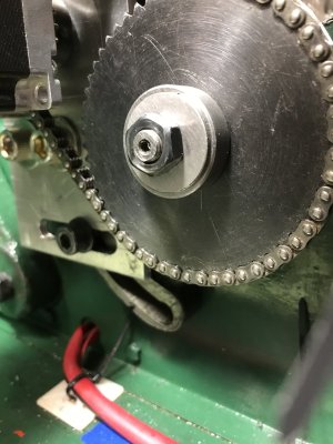
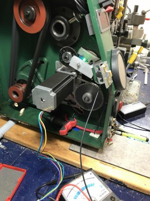
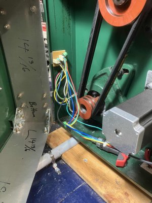
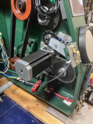
This week's adventures. Mounted the NEMA 23 motor on to a 1/4" aluminum plate, attached to the change gear banjo. Seems to be very solid, no wiggle. Instead of using the change gears, I dragged an old silent chain set from my scrap bin. Photos show the current set up. Not elegant, but it works and required no modification to the lathe.

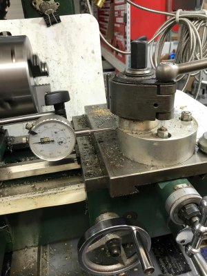
I was able to take a 0.030" cut on 1" steel bar, 210 RPM, using an Eccentric Engineering HSS tangential cutter. Bit was squealing, but chip was clean and I couldn't detect any stepper motor skipping.

This video was using my original change gear concept, and the mounting plate is only 1/8" aluminum sheet so it wobbled a bit. My backwoods torque concept was a spring scale attached between the cross slide and the tailstock. No problem getting 75 lbs of pull between stationary tailstock and moving cross slide. If I cranked up the stepper speed I could see it stutter, but only when it got above 60lbs of pull.

Photos of the plate, a sketch of the dimensions to match the banjo on my B2227L lathe and a NEMA 23 motor. My chain gearing is 75mm centers.

I wrote a spreadsheet to calculate stepper rpm and pulses versus spindle RPM and stepper driven/driver ratios. Some of the numbers looks scary, until you realize that the chances of my 3/4 HP 10x18 lathe cutting a 7 TPI thread at 1620 RPM are about the same as me being elected pope. At any reasonable speed & feed the stepper is operating at the left-hand side of the motor RPM/torque chart.


IMG_2634-1.jpg
 

Attachments

Much thanks to @jcdammeyer, his ELS board is just what I wanted (maybe more than I wanted).

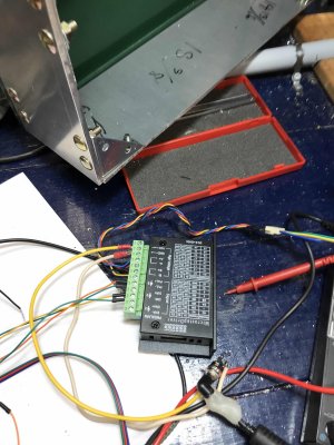
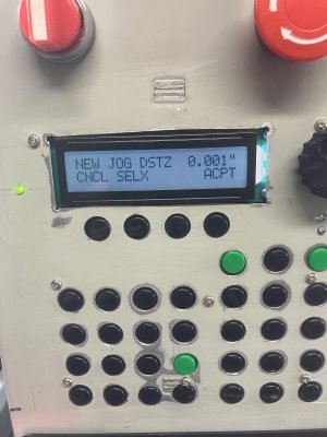
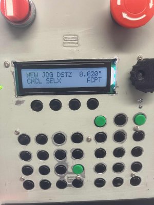
Mocked up today, video is it running using the jog function to move 0.020" back and forth in 0.001" steps. Poop, there's a lot of backlash in my lead screw! Good thing John's board can be configured to compensate.

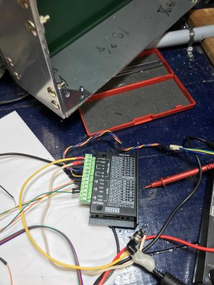
Took a bit to figure out the wiring, but once I got it got works brilliantly. Only ran the carriage into the tailstock twice, I'm a bit slow on the uptake sometimes.

Amazon should be delivering an enclosure in the next couple of days.

IMG_2642 (1).jpg
 

Attachments

  • IMG_2645 (1).jpg
    IMG_2645 (1).jpg
    423.2 KB · Views: 9
  • IMG_2643 (1).jpg
    IMG_2643 (1).jpg
    510.8 KB · Views: 9
  • IMG_2644 (1).jpg
    IMG_2644 (1).jpg
    491.1 KB · Views: 9
  • IMG_2646 (1).jpg
    IMG_2646 (1).jpg
    429.3 KB · Views: 8
The nice thing with a lathe is you really don't have to worry about backlash too much. With a lathe we always tend to cut in the same direction so it's not as much of an issue.

Just make sure your begin position is far enough away from where you start cutting if you decide not to use the backlash compensation.

If your lathe is anything like mine the leadscrew isn't evenly worn so backlash varies across the length.
 
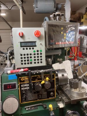
@jcdammeyer, 90% complete, cosmetic stuff needs to be done. I haven't decided exactly how I'll handle the front panel graphics. At this point I'm leaning towards engraving the tactile switch knobs rather than using the Mylar panel printout. I also need to clean up the bezel for the LCD display, since my measurements were f@#$%d.

$10 at Lees Electronics bought me 100 switch knobs in red/green/blue/yellow/black/white so I can make it pretty and group switch function by colour.

The case is a Value Village score, a metal cash box that's a perfect fit. Too bad it had a handle on the lid so I have some extra filling to do.

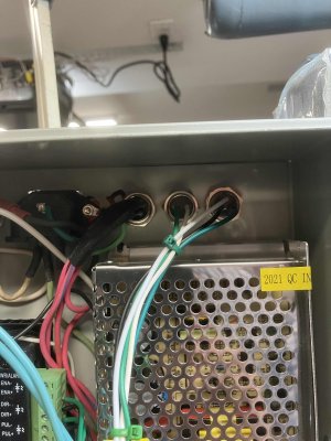
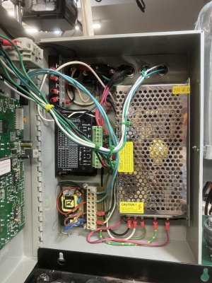
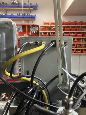
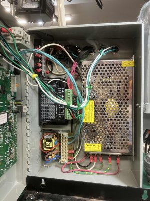
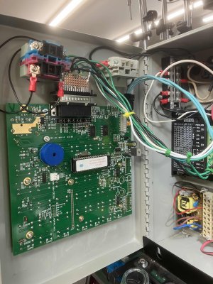
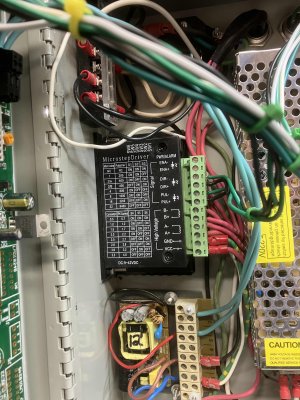
24VDC 5A stepper supply, NEMA 23 stepper, 12VDC walmart circuit board for the ELS board supply. E-stop on front of case, extra socket wired in for a limit switch (to be implemented later). If I decide to add a cross slide stepper I'll need to add another socket for motor leads.

IMG_3187 (1).jpg
 

Attachments

  • IMG_3193 (1).jpg
    IMG_3193 (1).jpg
    397.3 KB · Views: 8
  • IMG_3190 (1).jpg
    IMG_3190 (1).jpg
    535.1 KB · Views: 5
  • IMG_3186 (1).jpg
    IMG_3186 (1).jpg
    357.7 KB · Views: 5
  • IMG_3178 (1).jpg
    IMG_3178 (1).jpg
    449 KB · Views: 4
  • IMG_3177 (1).jpg
    IMG_3177 (1).jpg
    484.5 KB · Views: 4
  • IMG_3182 (1).jpg
    IMG_3182 (1).jpg
    514.8 KB · Views: 5
  • IMG_3185 (1).jpg
    IMG_3185 (1).jpg
    474.4 KB · Views: 5
  • IMG_3188 (1).jpg
    IMG_3188 (1).jpg
    298.1 KB · Views: 6
  • IMG_3189 (1).jpg
    IMG_3189 (1).jpg
    353.1 KB · Views: 7
  • IMG_3190 (1).jpg
    IMG_3190 (1).jpg
    535.1 KB · Views: 8
  • IMG_3191 (1).jpg
    IMG_3191 (1).jpg
    512 KB · Views: 8
  • IMG_3192 (1).jpg
    IMG_3192 (1).jpg
    512.6 KB · Views: 8
Will it need cooling? Nice box and super neatly done.
I don’t think it will need cooling, the stepper driver and power supplies are bolted to the case and I haven’t noticed any warmth during testing. Even the regulator on the ELS controller board seems to stay relatively cool. I have enough room in the case to add a small PC fan if needed.
 
Back
Top