• Spring 2024 meetup in Calgary - date Saturday, April 20/2024. discussion Please RSVP Here to confirm and get your invitation and the location details. RSVP NOW so organizers can plan to get sufficient food etc. It's Tomorrow Saturday! you can still RSVP until I stop checking my phone tomorrow More info and agenda
  • We are having email/registration problems again. Diagnosis is underway. New users sorry if you are having trouble getting registered. We are exploring different options to get registered. Contact the forum via another member or on facebook if you're stuck. Update -> we think it is fixed. Let us know if not.
  • Spring meet up in Ontario, April 6/2024. NEW LOCATION See Post #31 Discussion AND THE NEW LOCATION

Edmonton- Small lathe/milling work; Advice, insight, recommendation?

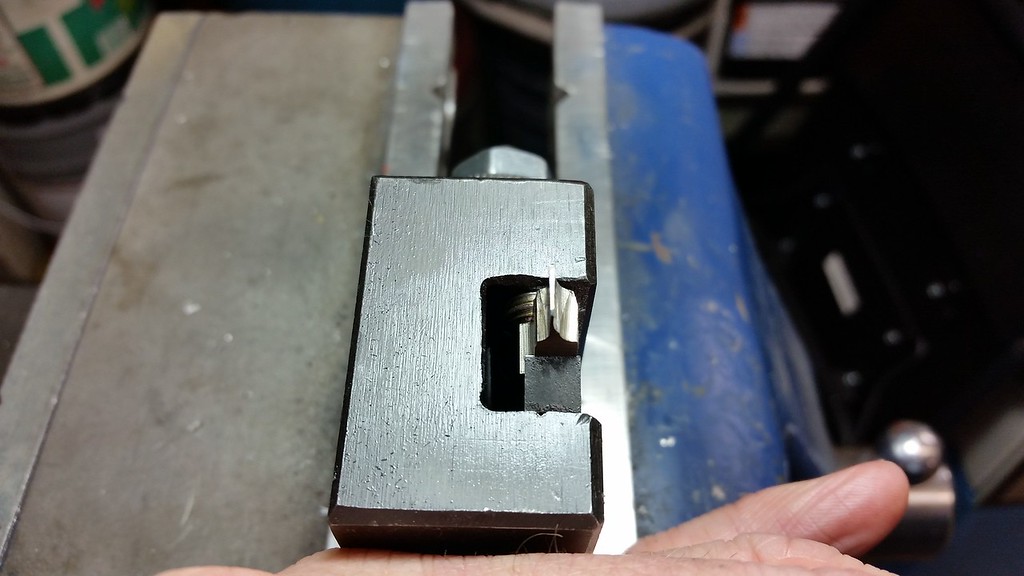
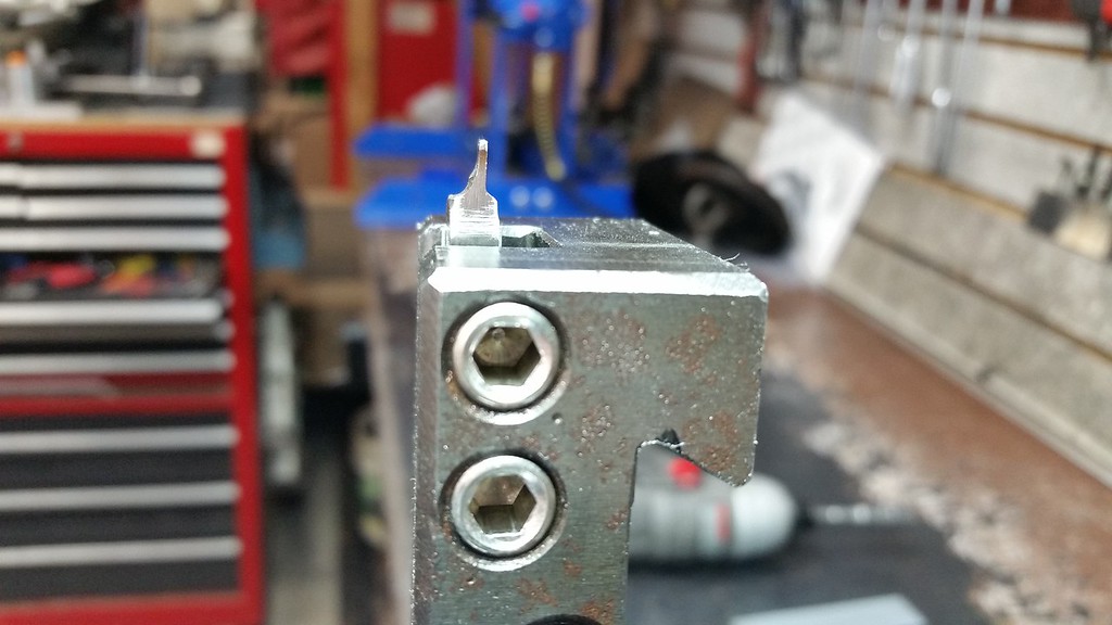
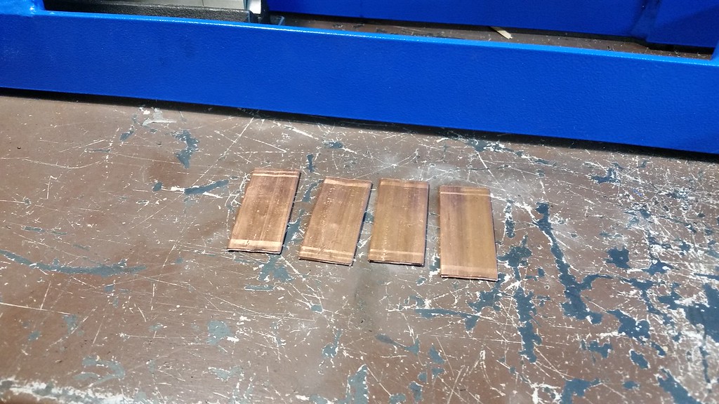
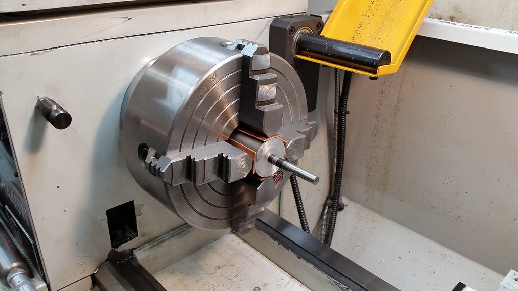
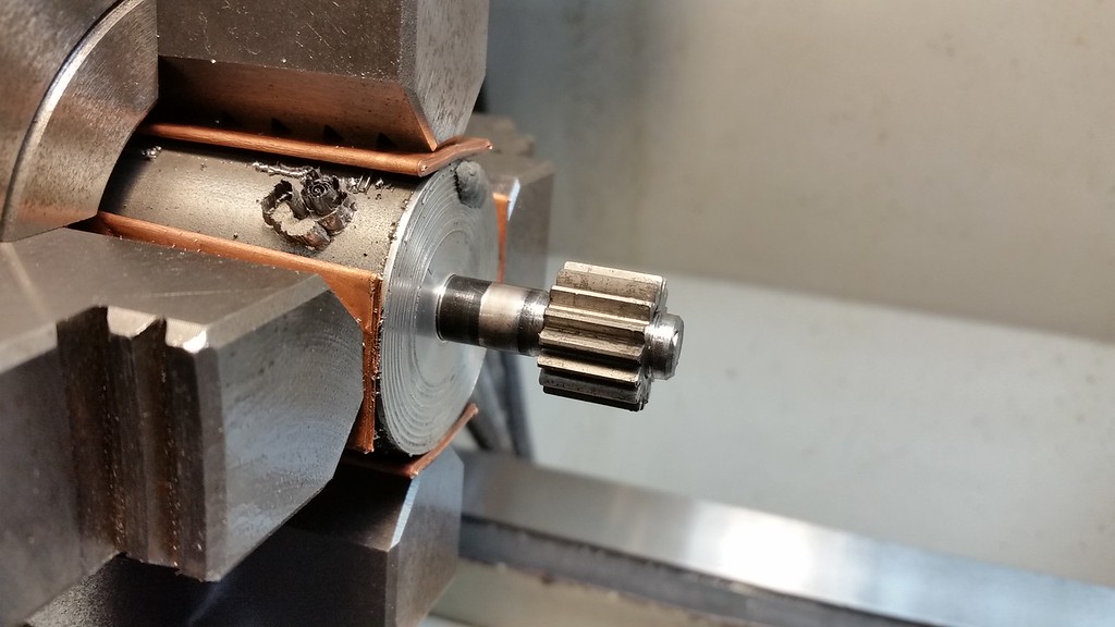
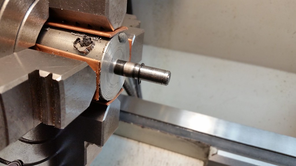
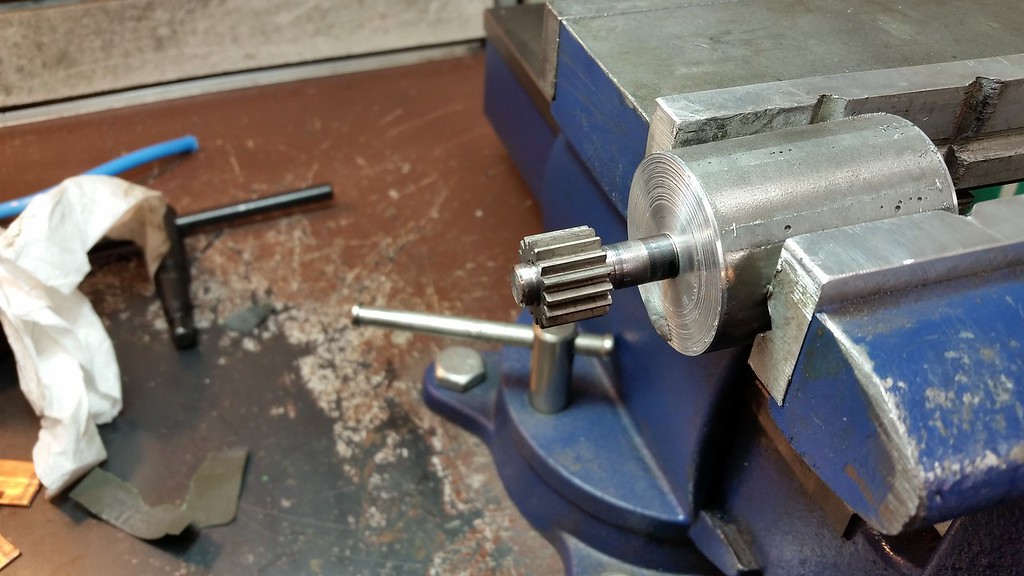
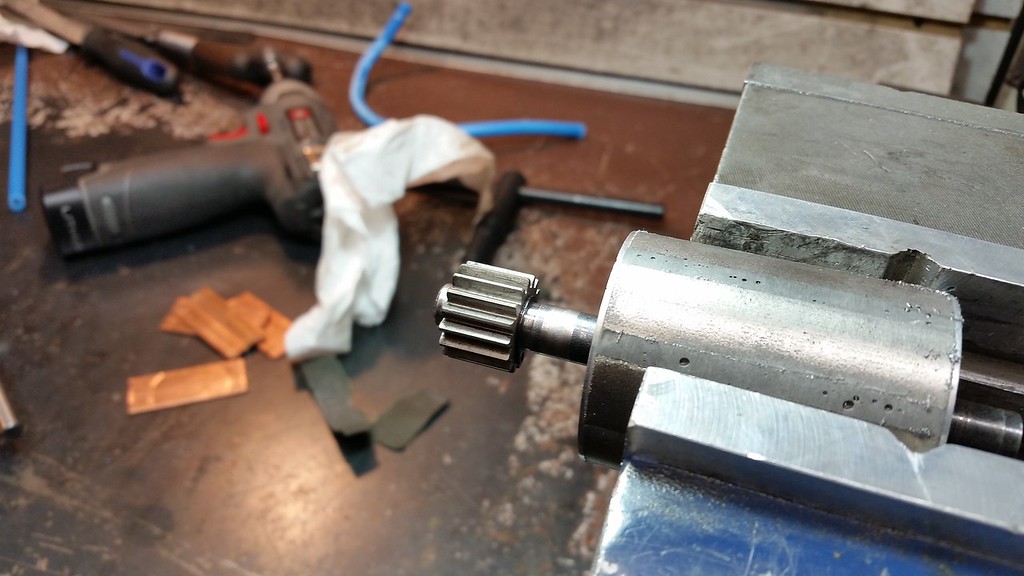
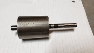
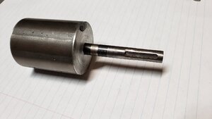
I have a shaft that I need turned and milled to some spec dimensions.

I have included a picture of the item. The surfaces of the narrower sections of the shaft need to remain un-marred because they mate with bearings. The wide sections of the shaft need to remain un-damaged since it is a fine tuned and balanced section of the unit. there are also some dabs of of material added to the flat ends of the wide sections that need to be undamaged- these are for further dynamic balancing. The wide section is also a strong magnet so that might pose some interesting challenges with cleaning the unit up. The unit is balanced and normally spins up to 10K+ PRM with no problems.

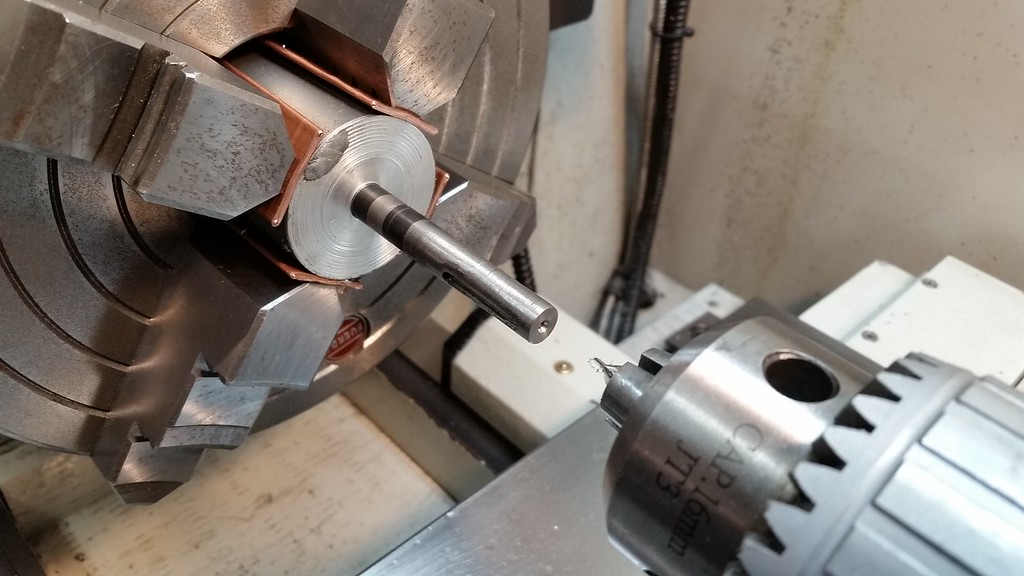
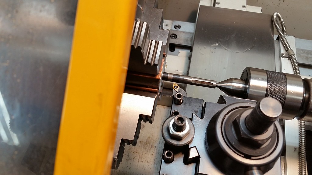
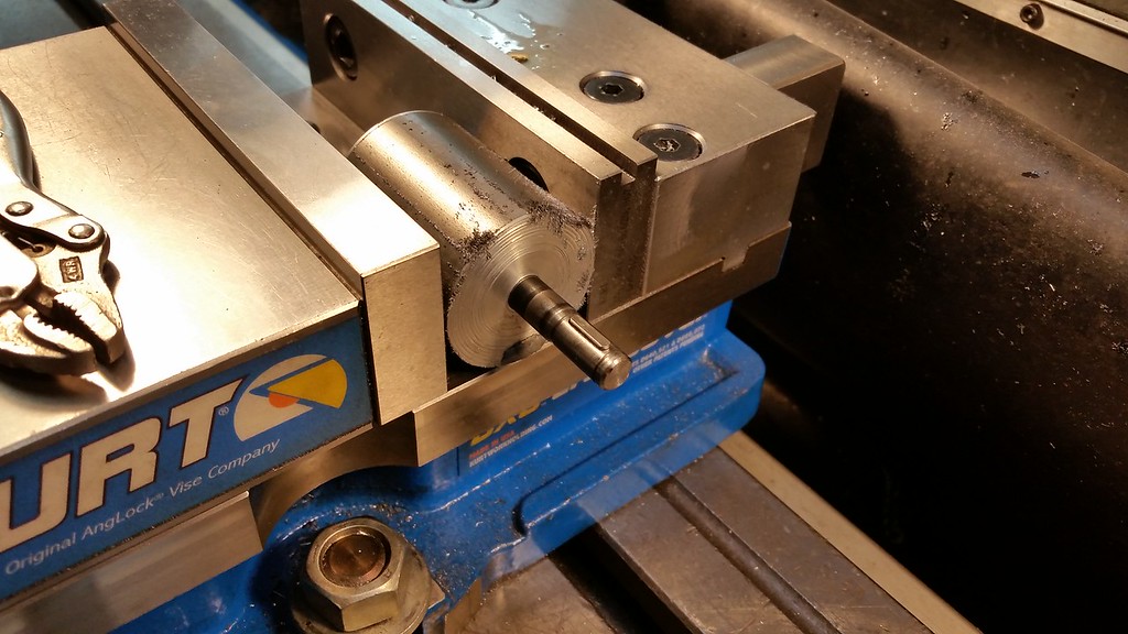
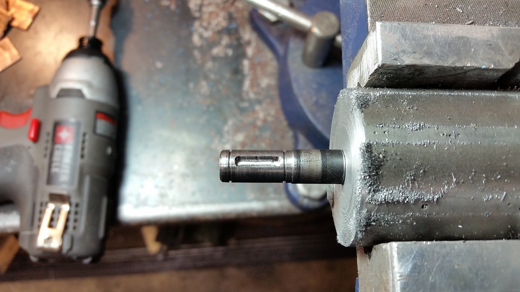
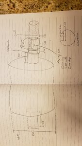
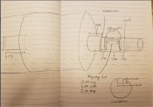
Any insight where a guy might find someone that can turn the narrow portions of the shaft to spec and also mill a centered keyway into the shaft?

I can also do up a 3d model or drawing in fusion if that's helpful.

Thanks!
 

Attachments

  • 20210506_000256.jpg
    20210506_000256.jpg
    300.1 KB · Views: 74
  • 20210505_223716.jpg
    20210505_223716.jpg
    198.2 KB · Views: 77
  • 20210505_223722.jpg
    20210505_223722.jpg
    194.3 KB · Views: 71
Last edited:

Janger

(John)
Administrator
Vendor
A few questions.

metric dimensions in mm?
Is that a steel shaft?
does the magnet come off? Press fit?
what machine is this for?
what do you want to spend?
Do you want a new shaft made or this one repaired?
 
Metric- Thanks for that, forgot to mention. I can't seem to find the edit function...

Shaft- Steel
Magnets- are bonded into the middle section. The outer flanges of the wide inner section appear to be press fit, but I'm not sure. None of it comes apart though.
This is the internal of an electric motor.

Spend- I was hoping this might be in the $100 range?

Seeing as how the unit is balanced and does not appear to come apart, I just want this to be modified.

Thanks for the response.
 

Janger

(John)
Administrator
Vendor
I’d want to see the part to confirm details. What is wrong with it? I don’t live in Edmonton it would probably be better done locally since it’s a repair. @John Conroy did you see this? Maybe you’d be interested?
 

Tom Kitta

Ultra Member
How precise do the cuts need to be? I.e. what is the tolerance? I assume you measured the current shaft and what you plan to do can actually be done dimensionally.

How strong is the magnet - is this just a rotor of a motor and nothing "over the top" - i.e. can you safely put it inside of late chuck without worrying about 200lbs magnet pull?

!! I just realized I omitted a critical measure- the new shaft diameter, I'll have to look this up once I'm home.

Regarding the precision, it's hard for me to say. I have no machining background so I'm not sure what is considered "high" tolerance. I was thinking in the area of 0.05mm, is that reasonable?

The 2 narrow 0.9mm grooves are for circlips retention (my circlips are 0.8mm so the 0.9mm ive allotted leaves a bit of leeway). The space between them is for a sun gear (that measures 13.50mm; I've allotted 13.60mm, again a bit of leeway) that is part of a planetary reduction assembly. The modified diameter of the shaft that seats the gear, needs to be within a certain tolerance so there isn't slop when the gear is seated (just realized I didn't state the the new shaft diameter...), and also for the Key pin recess to seat without backlash etc.

Correct, it's the rotor, it's strong, not outrageous though. What you would have to watch out for is the initial placement. As you get closer and closer to seating it, it would slap against the chuck possibly.
 

PeterT

Ultra Member
Premium Member
I rotated the picture for you.

But I'm still confused. Are you wanting a new inner (smaller) shaft machined to your dimensions & then you will be removing the large diameter magnetic? element and similarly attaching that to new shaft? Does the existing small shaft go straight through the large element? If so then you will need to define total length (inclusive of the big element). Or do you mean RE-machine the small shaft element on right hand side & the left shaft segment is just for info purposes? If so does the shaft have conical center drills cones in either end from original machining

I'm no motor expert by any stretch but some smaller ones I've seen, the shaft is either integral or stuck on really well with interference fit & retaining compound, because all the power is transmitted through that surface & the motor must withstand heat.

It would be more useful to others to specify the bearings being used because that will then define both the diameter and allowable tolerances. And be really certain about your fits because, if I understand correct, 13.60-13.50=0.1mm = 0.004" (sorry I have to think IMP) that is a healthy wide allowance for gear bore ID : shaft OD fit.
 

Attachments

  • 2021-05-07_22-10-33.jpg
    2021-05-07_22-10-33.jpg
    62.2 KB · Views: 41
I rotated the picture for you.

But I'm still confused. Are you wanting a new inner (smaller) shaft machined to your dimensions & then you will be removing the large diameter magnetic? element and similarly attaching that to new shaft? Does the existing small shaft go straight through the large element? If so then you will need to define total length (inclusive of the big element). Or do you mean RE-machine the small shaft element on right hand side & the left shaft segment is just for info purposes? If so does the shaft have conical center drills cones in either end from original machining

I'm no motor expert by any stretch but some smaller ones I've seen, the shaft is either integral or stuck on really well with interference fit & retaining compound, because all the power is transmitted through that surface & the motor must withstand heat.

It would be more useful to others to specify the bearings being used because that will then define both the diameter and allowable tolerances. And be really certain about your fits because, if I understand correct, 13.60-13.50=0.1mm = 0.004" (sorry I have to think IMP) that is a healthy wide allowance for gear bore ID : shaft OD fit.

UPDATE: Desired re-machined shaft OD=8.95mm (when I measure an internal casting I made of the spur gear bore with my calipers)

Thanks for rotating the image.

I'm not looking to disassemble any of the unit. The existing shaft is integral to the larger element. I don't even think it can be disassembled without destroying it. Re-reading my last post I see how i might have confused things by saying "new shaft diameter", I should have said "re-machined" as you did...

You are correct in : "RE-machine the small shaft element on right hand side & the left shaft segment is just for info purposes";
The portion of the shaft on the left side just extends through and I illustrated for reference I suppose. No modifications needed there.

I do not see any conical center drill cones in the shaft.

Regarding the 13.50mm measure is not a bore measure. It is the length of the spur gear.
The desired re-machined shaft OD=8.95mm

Regarding the bearings fit you refer to, the bearings will sit on the left shaft which is unmodified, and the left-most portion of the right shaft which is also unmodified, which measures 13.90mm. Unmodified OD=9.50mm.
 

John Conroy

member
Premium Member
I could machine that armature shaft for you. There are a few things that I would need to know. I would want the sun gear in hand for measuring. How much power does the motor have and what does the planetary gear set drive? Which element of the gear set is the output? You mentioned 10,000 rpm. Is that motor rpm or the speed of the output component? Since the planetary sun gear is the input, the output is going to be driven at a reduction or an overdrive depending on wheter the planetary pinion carrier or the planetary ring gear is the output. Either way, I would think that the sun gear should be a press fit onto the shaft. Is the motor variable speed? Will there be shock loads on the sun gear or will it be ramped up and down in speed gradually?

To achieve the best accuracy it would be nice if the small diameter end could be center drilled. Would a small drilled centering hole in the end of that shaft have any negative effect?

How soon do you need this done. My shop is full of disassembled motorcycles right now and it will be a week or so until I can take on a machining project.
 
Last edited:

Janger

(John)
Administrator
Vendor
It’s a group project! ;) 1 machinist and 77 arm chair critics! Ha

More pictures 12 carbon. What is your name anyway? Partiallly assembled with those gears and shots of the motor and what it goes into. what machine is it for? We always like machinery photos.
 
Last edited:
@John Conroy

The motor is https://www.astroflight.com/3220-astro-brushless-motor-details.html
In my application the motor can see about 10,500rpm motor speed. Input into the planetary gear set, gets the output shaft of the planetary reduced to 1/6th which then feeds into a chain drive that reduces a further 1/6th.
I dont see a problem with a small drill hole in the end of the shaft.
My timeline is sooner the better :cool: but I'm happy and grateful to wait patiently for any help I can get.
A shop with full of motorcycle parts sounds like the right kind of shop! This toy is my "motorcycle" now that I have kids and need life insurance lol.

@Janger
It's for a electric downhill bike.

I had it mated to a very impressive cycloidal drive initially. https://tangentmotors.com/tangentsdrive But that got chooched, and the engineer that crafted that device has moved on from that project so there is no more support for it. I'm now in the process of mating a planetary reduction to the motor which is a more off-the-shelf part instead of a rare limited run type product.

In my case it could see maybe 6000W peak for a short duration. This gets the motor spinning but then the reduction gives me the torque I need to get going. The motor is variable speed, there can be some shock to it. I would prefer the sun gear not be press fit so that it can be repairable etc. The whole planetary gear assembly with the sun gear is an off-the-shelf part that is designed for exactly the same application that I am using it for. Its just that I already have a motor that I would like to keep, it just needs some mods to get me there.


This group project seems to be going better than those I remember from grade school lol :p


pic 2.jpg
 

John Conroy

member
Premium Member
Andrew, now that I look at your drawing more closely I see that the end of the shaft is going to be parted off anyway so the centering hole will be on the discarded part of the shaft. Press fit is a relative term that varies depending on need. To make the sun gear to armature contact area last, there needs to be zero clearance between them. The damage I see around the existing keyway is the result of clearance where there should be none. If easy disassembly is required then a light sliding fit should be the goal (durability will be compromised). If you can supply the sun gear and key for measuring and test fitting that type of fit can be achieved.

This job would require me to make a one off cutter for the snap ring grooves so a sample snap ring will be required also.

If you want to go ahead with it PM me and we can arrange details.
 

ShawnR

Ultra Member
Premium Member
It’s a group project! ;) 1 machinist and 77 arm chair critics! Ha

More pictures 12 carbon. What is your name anyway? Partiallly assembled with those gears and shots of the motor and what it goes into. what machine is it for? We always like machinery photos.

And one silent observer....
 

John Conroy

member
Premium Member
Andrew dropped off the armature, sun gear, snap ring and key for me yesterday. I got at the job this afternoon. First I had to grind a HSS tool to cut the snap ring groove. They are only .029" thick so I ground a 1/4" blank to .030" wide and have 1 degree rake on all the faces and tested it on a piece of cold rolled scrap and it cut well. I was happy as I've never ground a cutter this small before, it was a test for my eye sight.


I wanted to mount it in a 4 jaw so I made some copper shims from 1/2" pipe to prevent marring the shaft.


The original shaft OD was .375 and the ID of the new gear is .355 so there was not much to take off. My goal was a hand push interference fit and it took quite a while to get that, the last .0003" removed with 400 grit sand paper. the groove cutter worked flawlessly and I cut the 2 grooves to .045" smaller OD than the shaft OD.


I parted the shaft off at the end of the original key slot.


Then over to the mill where I used 3/32" end mill to cut the 3mm key slot.


The magnets are so strong that you almost don't have to clamp it in the vise, it just sticks there.


Last edited:
@John Conroy Big thanks John for your efforts! Also, thanks to the group and those that had a look in on the thread!

Was a pleasure meeting you and getting a glimpse of your shop.

Turned out nicely!

Tip:
Being a very strong magnet I was initially a bit worried about how I would clean the shavings and dust off the unit. Duct tape saved the day once again!
 
Top