Hi DavidIs there no silkscreen on the old board to cross-reference to the new board?
Not that I can read in the instructions. They'll probably send me a mapping diagram later today. Their support has been really good so far.
Hi DavidIs there no silkscreen on the old board to cross-reference to the new board?
Steppers are pretty simple. Usually 4 wires, which make up two pairs. To figure which are pairs, connect any two motor wires together and try to turn the motor. If it doesn't turn, that's a pair. If it does turn swap one of the wires out and it should not turn.Day 10
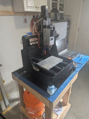
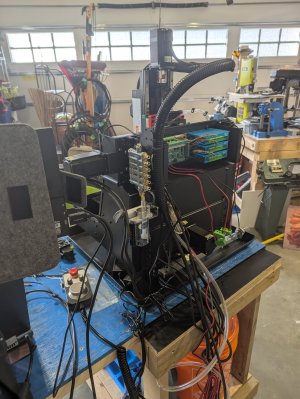
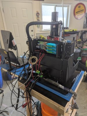
Electrical box attached to the frame, internal components installed and wiring started. Just need some clarification as the motor wire colors are different between the motors and instructions.
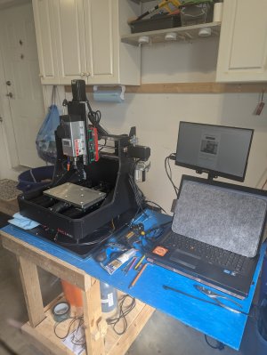
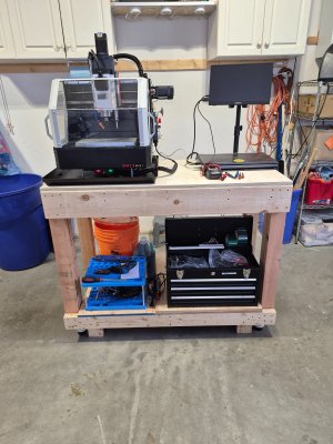
The tray came from Amaz. WirthCo 22x22. A bit pricy but it'll last. My Machine came with a vise and pins to hold it in place, but I'm planning on a fixture plate as well.Nice, I have a question or 2:
Where did you get the drip tray? Its a better fit than the Costco one I got (but was only $9).
And what are you planning on doing for work holding? I made a little fixture plate, but I want a vise type device as well, either modular jaws for the fixture plate or a low profile vise. Just looking for what others are thinking.
Not just yet. I did the wiring pre checks and didn't like what I saw. Might have a bad connection so I'll get my electronics guy to double check. Meanwhile I'll get Mach3 all setup and ready to go.Looks good. Are you ready to make chips?


 pics
picsYes, I discovered a couple of wiring issues. All fixed. X, Y and Z all work. Now to tackle the Spindle, VFD and tool height gage. Good thing I'm retired or this machine wouldn't be ready until December. Lol34v is fine,
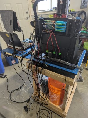
I think I've spotted a difference in the wiring of the encoders, the one in your hand is black-ground, red-vcc. the other 2 look like white-ground, red-vcc.
I’d do a google search for how to calibrate Mach 3Hey Mike R and anyone using Mach3
I'm finally up and running, or almost. I ran the provided bed leveling program from fusion and it almost worked. I have to make the holes again which is not an issue, but they are coming out at half the required diameter.
I checked the Set Steps per Unit, and that's all good.
I also rechecked the fusion file and that looks OK.
Any suggestions?
Thanks Mike. I have it working finally. Just need to fine tune the probe and tool setter.Double check your switch settings on the stepper driver, it could be set for double the number of steps per rev which would give you the results you are seeing.
Looking back - mine is set to this starting with switch 1:
OFF, OFF, ON, ON
This corresponds with 1600 steps per rev. everything else is OFF except switch 7 which enables the closed loop control.
View attachment 63958