• Scam Alert. Members are reminded to NOT send money to buy anything. Don't buy things remote and have it shipped - go get it yourself, pay in person, and take your equipment with you. Scammers have burned people on this forum. Urgency, secrecy, excuses, selling for friend, newish members, FUD, are RED FLAGS. A video conference call is not adequate assurance. Face to face interactions are required. Please report suspicions to the forum admins. Stay Safe - anyone can get scammed.

Dividing head restoration

Great progress! Once I pushed the pin out a few more thou it was no longer locking the brass bushing and worm gear in place. Now mostly disassembled!

Sorry I wasn't able to make this problem more clear. My old software I used for adding labels to pictures no longer works on the new windows and I haven't yet found a suitable replacement. In the pic in my previous post you can just barely see the pin sticking out a mm on the upper right hand side of the cylinder that holds the worm gear. At the top of the cylinder you can see the worm gear shaft protruding. The brass bushing is slightly recessed into the inner bore and you can see a couple of slots in the brass transecting the gear shaft. Probably clear as mud?

View attachment 24296

Actually quite clear. I seem to have difficulty understanding lots of stuff others say on here. Yours was just fine.

Glad you made more good progress.
 
Looks like I'm going to need an adjustable pin spanner to remove the last couple of parts from the back of the worm gear assembly. While I wait for that to arrive I think I will start cleaning up the parts.

DSC_0015 (3).JPG
 
Looks like I'm going to need an adjustable pin spanner to remove the last couple of parts from the back of the worm gear assembly. While I wait for that to arrive I think I will start cleaning up the parts.

View attachment 24304

I assume you need/want the tool anyway and didn't want to make one.

I like to make these out of the head of a bolt. I use Bolts all the time as stock for my lathe. Its cheaper than buying steel. Then I have left over bolt heads.

I use a bolt head the right size for the job, then drill it and thread it for two 1/4" grub screws. I also chuck the grub screws and turn their noses down to fit the holes in the part I want to loosen or tighten.

The reason for using a bolt head is to facilitate a wrench or socket.

Need a pic in order to visualize that........
 
Need a pic in order to visualize that........

Here is one I posted earlier. It's a big one, and it needs the center bored out, but it shows the idea. And yes, farmers need BIG nuts.

Post in thread 'Bridgeport Project' https://canadianhobbymetalworkers.com/threads/bridgeport-project.3521/post-48818

Basically, you custom make them for the job at hand and then set them aside as part of the tool kit for whatever thing you needed them for. Sometimes they need a flange, sometimes a collar, sometimes a bore. The common feature is an outside hex to get a regular wrench on, they are stronger than a spanner, and they are cheap cheap cheap.
 
Last edited:
Here is one I posted earlier. It's a big one, and it needs the center bored out, but it shows the idea. And yes, farmers need BIG nuts.

Post in thread 'Bridgeport Project' https://canadianhobbymetalworkers.com/threads/bridgeport-project.3521/post-48818

Basically, you custom make them for the job at hand and then set them aside as part of the tool kit for whatever thing you needed them for. Sometimes they need a flange, sometimes a collar, sometimes a bore. The common feature is an outside hex to get a regular wrench on, they are stronger than a spannner, and they are cheap cheap cheap.

I don't have any bolts that big kicking around! I would have to borrow some from my local hydro tower! :D
 
I don't have any bolts that big kicking around! I would have to borrow some from my local hydro tower! :D

Anyplace with big machinery will have them laying around.

And like you say, I'd bet Hydro, has them. And prolly the municipality, farm supply stores, used farm equipment yards, rail yards, ship yards, etc etc have them laying around too.
 
There's trouble in paradise! I've been cleaning up parts on my DH and testing assemblies for fit and freedom of rotation. All was well until I got to the main body and the rails its supposed to turn on in the base/cradle. These two main parts were very difficult to pull apart and required considerable force to separate. I reasoned though that it was just dirt grime and corrosion and a lot of cleaning would solve the problem. Bur now I've cleaned and cleaned until I could do no more with the rails that these parts are supposed to rotate on and still these two parts only come together if they are forced. No way they're gonna rotate like this I thought. There must be something wrong! So I decided to make some measurements to better understand what was going on.

So as it turns out the part on the main body that rides the rails on the cradle measured an even 4.723 inches wide (120mm) all around. The rails on the cradle however were a different matter! On the cradle the rail measured the same 4.723 in the middle, but just 4.712 on the chuck side (the front side in the pic and the top of the fork), and only 4.718 on the oppsite side behind the chuck. To make a long story short the rails on the cradle are too narrow and not exactly parallel. The rails are as much as 11 thou too narrow at the top of the forks where the chuck goes on!

My theory is that this device was once seriously abused with a hammer causing the cradle to slightly deform. You can still see the numerous hammer marks on the back (the right side in the pic)!

Now what do I do???

zDH cradle.JPG
 
If it has been bashed, then the cradles might also be out of alignment a little bit. but fixing that comes much later...

Starting with it being cast iron, we have to go gently. if someone bashed it, there will be stress fractures in the casting. If malleable iron or cast steel, this won't be as much of a problem, but let's assume the worst case for a minute.

Induced stress in a cast part can be somewhat relieved by heating and cooling cycles. You can also stress relieve grey iron using mechanical means - percussive maintenance... You hang it buy a rope or chain, and whack it with a wooden mallet from all angles several hundred times... Heating an cooling can also have a beneficial effect, I have seen guys recommend heating to 450-500 degrees, but my 'old school' Dad said that 250-300 degrees, then slowly cool, then repeat. Measure every 3 or so cycles, and certainly after whacking it with a wooden lmallet. Your casting will only move so far. any further remedy has to be by machining.

11 thou is a lot. You can then make a setup and using a boring head to dust the gimbal. You have to have the piece indicated in to a very high tolerance before boring or you will ruin the part. It is not unreasonable to be square to 2 tenths before proceeding.

You are lucky in that you know what surface is out, so the other gimbal is your reference surface.
 
My initial thinking went along similar lines to what @Dabbler recommended. Some stretching some heating, some tapping to get it back into shape. It dawned on me though that I needed to know just how bendable or malleable CI really is. So according to Google I found CI isn't very malleable at all and more likely to crack than adopt a different shape! I had made a simple device from some scrap all thread to stretch the cradle a little. After several cycles of strectching, heating and tapping I found the cradle just relaxed back to its original shape. I decided to do a couple of tests to see if the cradle is real grey CI or more malleable iron. The first test is to make a dimple with a punch. If malleable iron a ridge should form around the perimeter of the dimple detectible to the touch. If CI no ridge around the dimple is formed. On my piece no ridge was detectible. For the second test the dimple wqs drilled. If malleable iron a bit of stringiness in the swarf should be detectible. Otherwise only a powder is formed if it is CI. On my piece only a powder was formed. My conclusion is that my cradle is worst case CI and the best solution would be to machine it. I have no idea how I will be able to machine it to that degree of accuracy however! I wish my mill was working!
 
Is the base flat?

Here is what I think happened: they torqued the mounting bolts (DH to table mounting bolts) really hard with crud under the sides and thus stressed (bowed?) the center of the cradle. There is no way that the cradle moved with the DH fully assembled as the insides are hard against the shoulder of the rotating element when assembled. The cradle only moved after you pulled out the rotating element.

I would try and assemble it. Well lubed, it may still allow you to rotate it. Yes, 11 thou is a lot. But there is large surface area where the inside makes contact with the shoulder on the rotating element. Once assembled, it could well be that it ends up just snug.

I would use some form of jacking screw between the cradle ears and try to put it back together. It may yield easier than you think.

It was together, so it will go back, especially since you cleaned it so well.

Then I would again check the base for flatness. Adjust as required while using the DH to not put more stress into the CI going forward.

Machining it could be problematic as you may relieve even more stresses and make the whole thing worse.
 
Looking at the cradle, you could bolt it to a stout piece so angle using bolts in the through holes at the front (where the “ears” lean in the most) and use a small shim under the center mounting slot area (maybe 5 thou thick). Then tighten up the bolts slowly and it should spread the uprights apart enough (you can measure your progress) and the rotating part should drop right in.

You could also put the whole set-up (with the angle iron bolted to it) on the BBQ for some heat cycles to try and bring it back to the original “neutral“ position. You may have to open the ears just a bit more to get the final parallelism so it stays there once the angle strap is removed.
 
The base appears to be almost perfectly flat, within a thou, although heavily scratched and worn out of spec around the edges.

zDHbase.JPG
 
Due to health issues it's been Christmas since I have been able to find the strength and energy to do anything in my shop. It hasn't stopped me from thinking about my many projects however! In the case of the dividing head I came to the conclusion that trying to force the body back into the cradle would probably cause something to break. My only option therefore would be to remove a small amount of cast iron from the cradle until I achieved a proper fit. No matter how much I racked my brain tho I couldn't decide how best to do this accurately without a functional milling machine.

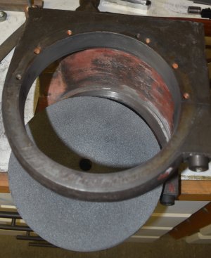
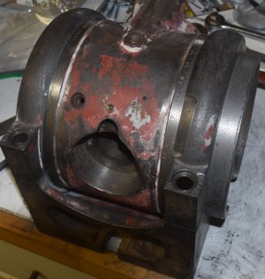
Then at the recent meetup in Pickering Tom (professional machinist) suggested I go at it with a hand file. This inspired me to get out to my shop and have some fun! I pulled out the dividing head and some appropriate files. I realized my straight files would not fit in to some of the nooks and crannies but I imagined an 8 inch grinding wheel might do the trick. The grinding wheel turned out to be a perfect size and I went at it with files and grinding wheel. Little by little with perseverance and frequent rest breaks I got the body to fit nicely into the cradle albeit still maybe a little tight. But this raised the question: how tight should a dividing head be in its cradle? Should it turn freely or should it be a tight fit. After all the body has to be secured solidly in its cradle during machining operations so surely a loose fit is not desirable? How tight are your dividing heads? How easily do they turn in their cradles?
 

Attachments

  • DSC_0123 (2).JPG
    DSC_0123 (2).JPG
    397.7 KB · Views: 10
  • DSC_0124 (2).JPG
    DSC_0124 (2).JPG
    471.4 KB · Views: 10
The third option. A light friction fit. This forms the basis of accuracy and should be as high contact as possible. When you clamp it, there will be some elastic averaging, but not very much.
So what would be a good way to achieve a high precision fit in this case. I am considering trying a little lapping using something like the Lee Valley lapping grits.
 
. I am considering trying a little lapping using something like the Lee Valley lapping grits.
If you are lapping cast iron, some abrasives, such as diamond or silicon carbide will embed themselves into the cast iron. This would not be good in the long run.

You can do so much with 00 and 000 files, and 900 - 4000 grit sandpaper on wood. I've never tried abrasive compounds on cast iron because of the fear of embedding. Nowadays, you can get even finer grades of lapping film from 3M. Lee Valley used to carry a sampler.

There is always scraping. Scraping leaves desirable voids for oil to sit in, creating a very long lasting wear surface.

More important than how you are removing metal, is how you are measuring where to remove it. And deciding which piece to remove it from. :confused:
 
If you are lapping cast iron, some abrasives, such as diamond or silicon carbide will embed themselves into the cast iron. This would not be good in the long run.
Presumably then the embedding of abrasives into the cast iron would also occur with sandpapers or grinding disks that incorporate diamond or silicon carbide abrasives?
 
Back
Top