• Spring 2024 meetup in Calgary - tentative date Saturday, April 20/2024. Other regions are also discussing meet ups. If you want one in your area get going on organizing it! discussion
  • We are having email/registration problems again. Diagnosis is underway. New users sorry if you are having trouble getting registered. We are exploring different options to get registered. Contact the forum via another member or on facebook if you're stuck. Update -> we think it is fixed. Let us know if not.
  • Spring meet up in Ontario, April 6/2024. NEW LOCATION See Post #31 Discussion NEW LOCATION

Converting Mini Mill to CNC

Jwest7788

Joshua West
Administrator
So I have the X axis and the y axis moving now. Here is a picture of what the drives looks like.
View attachment 869
Everything works good so it is ready to use for drilling bolt patterns and doing some basic milling. Later I will finish this project by hooking up the stepper motor on the z axis.
What was the thought process behind gearing up like that? More speed I guess?

Any torque issues?


Sent from my iPhone.
 

kylemp

Well-Known Member
I would assume one of, or a combination of, torque and/or accuracy and/or offsetting the motor for clearance.
 

Alexander

Ultra Member
Administrator
I wanted to uses direct drive instead of gearing it down the way i did. This setup is actually twice the torque and half the speed. There is the added benifit of having the big stepper tucked away instead of having it sticking way out the front. I really am only running this setup to get the torque reuired from this machine. There isn't tons of power as it is but enough for sure. I will keep you posted on its capabilities as i go.
 

Janger

(John)
Administrator
Vendor
I bought this mill from Alex. I am super pumped this is really cool. I need to add the Z-axis and I was looking at spindle speed control options. Loads of things available on ebay.

https://www.ebay.com/itm/10HP-7-5KW...185275&hash=item56a04e6169:g:VCMAAOSwtplZw37a

Would something like this VFD work? It is made in China - cheap - no idea if this would suit. It claims to have analog control input so I can imagine some sort of Mach3 control which would be really nice. The mill is a 2HP unit but single phase. This VFD says its 3 phase output - sounds like this particular model would not work. Yes? No?

On ebay I see lots of used VFDs of various kinds prices all over - what do I need? What have other people bought?

Making T Nuts.
 
Last edited:

kylemp

Well-Known Member
All vfd's need a 3 phase motor to output to.. so you'll need to find a 3p motor even if the vfd is single phase in.
 

kevin.decelles

Jack of all trades -- Master of none
Premium Member
I have a couple of vfd a like that, no issues from the limited work I've been doing . I don't know if I'd use it on an expensive machine but for the motors and machines I run I can't justify brand name

I have two of the huang yang units. Ebay


Sent from my iPhone using Tapatalk
 

Alexander

Ultra Member
Administrator
Great video. I think that face mill has a 90 degree solder so you can rough the step using the face mill next time and finish with the endmill.
 

Janger

(John)
Administrator
Vendor
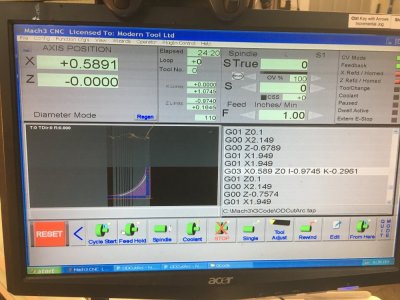
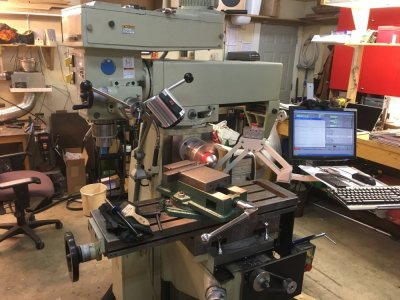
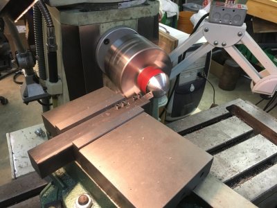
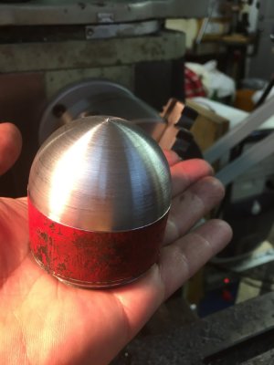
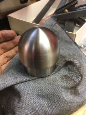
Well everybody next update on Alex's mill. It's my first CNC machine - loads to learn wow. The mill has a 4hp horizontal spindle as well which is powered by a separate motor. I realized I could buy an R8 5" chuck, mount it on the horizontal, and with some ingenuity and mach3 configuration turn it into a limited CNC lathe. I got the chuck at KMS mounted it and got started. Fortunately I had a skeptical Alex over to help get the initial program going and I was encouraged with his help that this was actually going to sort of work. I had lots of config to do first with the motor setup and such - I had both axis going the wrong way and other problems but eventually it came together.

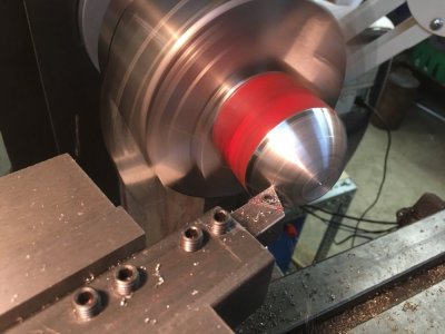
Below you can see some pictures. I'm still really learning the feed and depth of cut settings - I've had several crashes already but it does seem to work. You can see the weird tool holder I made gripped in the swivel milling vise. This is to keep the vise well away from the jaws on the chuck. I also seem to either set the depth of cut way too deep and it crashes or way too shallow and it takes forever to do anything. I can see the need already for variable spindle speed control. If you look closely on the part you can see a nicely finished section and then rougher towards the axis. I believe this is because the surface speed slows down as the tool progresses inward on the X axis.

It's possible I could make a tailstock of sort to mount in the other end of the ram which would normally support an arbor for milling out gears or key ways with horizontal milling cutters. The real limitation to this is length of travel on the Z axis. It's just really short once the chuck is mounted. The whole setup has rigidity issues too of course. Still CNC Lathe!

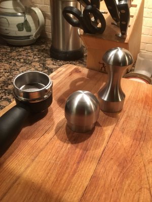
What is it? It's a coffee tamper... :>

The next thing to do on this project is motorize the Z milling axis. Maybe over Christmas.
 

Attachments

  • IMG_2624.JPG
    IMG_2624.JPG
    140.6 KB · Views: 20
  • IMG_7858.JPG
    IMG_7858.JPG
    156.9 KB · Views: 21
  • IMG_9311.JPG
    IMG_9311.JPG
    141.8 KB · Views: 20
  • IMG_6430.JPG
    IMG_6430.JPG
    97.7 KB · Views: 18
  • IMG_9756.JPG
    IMG_9756.JPG
    82.7 KB · Views: 18
  • IMG_5773.JPG
    IMG_5773.JPG
    181.9 KB · Views: 16
  • 18A2E218-A089-4FEF-A37A-F4D1B3ABFC66.jpeg
    18A2E218-A089-4FEF-A37A-F4D1B3ABFC66.jpeg
    138.9 KB · Views: 15
Last edited:

Janger

(John)
Administrator
Vendor
Started working on the Z axis automation finally... I needed gears to work with the 8mm toothed timing autobelt. Naively just did some math and started making gears in aluminium. After a couple attempts and not a precise enough fit I realized I should be modelling in CAD, printing in plastic to verify and then making gears. I ended up making a dozen revisions before I had it right. all kinds of information on the internet and none of it seemed quite right when I printed and tested. In retrospect another member pointed out round teeth are not how they do it on the car timing gears. That's true. Anyway I finally through trial and error mostly ended up with gears that fit the belt. I printed them up and decided to try them instead of making more aluminium ones.
Here are pictures of making the motor mounts and all the install steps.
 

Attachments

  • 05F239CC-2ABD-4BBF-9206-D8EEAA3367B5.jpeg
    05F239CC-2ABD-4BBF-9206-D8EEAA3367B5.jpeg
    197.7 KB · Views: 0
  • 1595442F-EE15-4548-BF73-5C4EF3CEAD52.jpeg
    1595442F-EE15-4548-BF73-5C4EF3CEAD52.jpeg
    116.8 KB · Views: 0
  • EC80C18E-7955-4FB5-9997-54FDCA60B0BB.jpeg
    EC80C18E-7955-4FB5-9997-54FDCA60B0BB.jpeg
    112.2 KB · Views: 0
  • DBE3FAE3-0923-4CE9-A917-ADFF29C0E46E.jpeg
    DBE3FAE3-0923-4CE9-A917-ADFF29C0E46E.jpeg
    114.5 KB · Views: 0
  • 9546618C-DD44-4978-A33A-E9C1581143FA.jpeg
    9546618C-DD44-4978-A33A-E9C1581143FA.jpeg
    107.7 KB · Views: 0
  • CB663E4B-00A5-43E9-ABA9-C2E0780575E9.jpeg
    CB663E4B-00A5-43E9-ABA9-C2E0780575E9.jpeg
    137.7 KB · Views: 0
  • EE2FE302-E8B2-46D2-BFE9-741286203787.jpeg
    EE2FE302-E8B2-46D2-BFE9-741286203787.jpeg
    140.7 KB · Views: 0
  • 4A6CAEAF-02B2-4B69-B68C-0568F661E478.jpeg
    4A6CAEAF-02B2-4B69-B68C-0568F661E478.jpeg
    152.2 KB · Views: 0
  • 5DBAEFE0-9A7F-472F-94FD-3E268E3E3C13.jpeg
    5DBAEFE0-9A7F-472F-94FD-3E268E3E3C13.jpeg
    109.7 KB · Views: 0
  • 88A52BE4-7059-4D02-8393-E8003F596BD2.jpeg
    88A52BE4-7059-4D02-8393-E8003F596BD2.jpeg
    120.8 KB · Views: 0
Last edited:

Janger

(John)
Administrator
Vendor
So after mucking about with configuration in Mach 3 I finally got it drilling. Amazing.... 36 1/4" holes for no particular reason. Half right through half blind.

Vids...
 

Attachments

  • 2B3FC37E-9830-478B-B3AC-D969AF895A72.jpeg
    2B3FC37E-9830-478B-B3AC-D969AF895A72.jpeg
    127.9 KB · Views: 0
  • 198CF602-CACE-4BF7-A646-2DAB327E6698.jpeg
    198CF602-CACE-4BF7-A646-2DAB327E6698.jpeg
    159.7 KB · Views: 0
  • 3927DDDE-6586-41A6-8258-EA5646FD9628.jpeg
    3927DDDE-6586-41A6-8258-EA5646FD9628.jpeg
    165.7 KB · Views: 0
Last edited:

Janger

(John)
Administrator
Vendor
So now that I can drill it's on to actual 3D milling. I modeled up this blue thing as a test part. It isn't anything really just a few features, posts, holes, slot. and I'm trying to go from Fusion CAD through the CAM cycle and get it into the mill and run the program. I've had a number of attempts. It's progressing but lots to learn in the CAM side, feeds, speeds, mill setup. Lots of screw ups...

This vijeo is REALLY loud. now AvE is teaching me to spell... :>
 

Attachments

  • E14B3332-4D9D-4730-99CB-27E3B789EE1D.jpeg
    E14B3332-4D9D-4730-99CB-27E3B789EE1D.jpeg
    115.9 KB · Views: 0
  • B79F7F0C-6AB6-4CE5-B57D-649FC3F361A0.jpeg
    B79F7F0C-6AB6-4CE5-B57D-649FC3F361A0.jpeg
    144.8 KB · Views: 0
  • E74B4C80-F26D-455B-B138-922DED0C2AD6.jpeg
    E74B4C80-F26D-455B-B138-922DED0C2AD6.jpeg
    121.4 KB · Views: 0
  • AD11918D-7033-4182-8F36-DA773CDA34B8.jpeg
    AD11918D-7033-4182-8F36-DA773CDA34B8.jpeg
    131.6 KB · Views: 0
  • IMG_3503.JPG
    IMG_3503.JPG
    64.3 KB · Views: 0
Last edited:
Top