TorontoBuilder
Sapientia et Doctrina Stabilitas
I promised to install the DRO on my brother's lathe within a week or so of his taking possession of the new to him Colchester Master 2500 lathe.
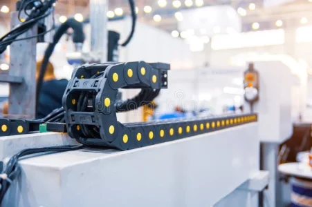
I previously ordered a 2 axis system with linear glass scales with travel lengths of 150mm (5.91") & 1000mm (39.37") for our previous 12x37" lathe and it should fit this new one just fine.
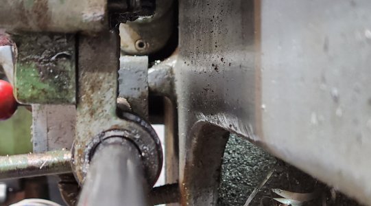
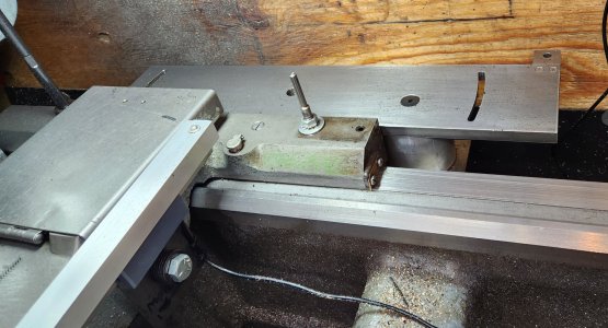
So as I understand things I need to mount the slimline scale to the cross slide, and the read head to the middle of the saddle. Or I may need to install the scale towards the rear of the slide and have the read head on the rear of the saddle.
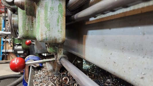
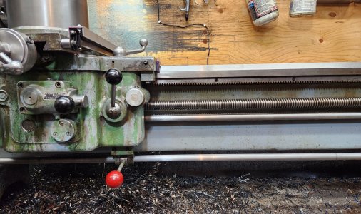
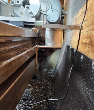
Then I need to mount the other scale to the backside of the lathe bed bellow the flat where the taper attachment normally resides, and the read head mounted to the rear of the saddle on the right hand side closest to the tail stock, where I've scribbled in yellow highlighter. This means installing a a long bracket and perhaps relocating the coolant arm mount.
It all seems simple enough, if I had working arms.
I don't think I'll recover from the effects of moving the lathe for at least 4 days.
I previously ordered a 2 axis system with linear glass scales with travel lengths of 150mm (5.91") & 1000mm (39.37") for our previous 12x37" lathe and it should fit this new one just fine.
So as I understand things I need to mount the slimline scale to the cross slide, and the read head to the middle of the saddle. Or I may need to install the scale towards the rear of the slide and have the read head on the rear of the saddle.
Then I need to mount the other scale to the backside of the lathe bed bellow the flat where the taper attachment normally resides, and the read head mounted to the rear of the saddle on the right hand side closest to the tail stock, where I've scribbled in yellow highlighter. This means installing a a long bracket and perhaps relocating the coolant arm mount.
It all seems simple enough, if I had working arms.
I don't think I'll recover from the effects of moving the lathe for at least 4 days.