-
Scam Alert. Members are reminded to NOT send money to buy anything. Don't buy things remote and have it shipped - go get it yourself, pay in person, and take your equipment with you. Scammers have burned people on this forum. Urgency, secrecy, excuses, selling for friend, newish members, FUD, are RED FLAGS. A video conference call is not adequate assurance. Face to face interactions are required. Please report suspicions to the forum admins. Stay Safe - anyone can get scammed.
-
Several Regions have held meetups already, but others are being planned or are evaluating the interest. The Calgary Area Meetup is set for Saturday July 12th at 10am. The signup thread is here! Arbutus has also explored interest in a Fraser Valley meetup but it seems members either missed his thread or had other plans. Let him know if you are interested in a meetup later in the year by posting here! Slowpoke is trying to pull together an Ottawa area meetup later this summer. No date has been selected yet, so let him know if you are interested here! We are not aware of any other meetups being planned this year. If you are interested in doing something in your area, let everyone know and make it happen! Meetups are a great way to make new machining friends and get hands on help in your area. Don’t be shy, sign up and come, or plan your own meetup!
You are using an out of date browser. It may not display this or other websites correctly.
You should upgrade or use an alternative browser.
You should upgrade or use an alternative browser.
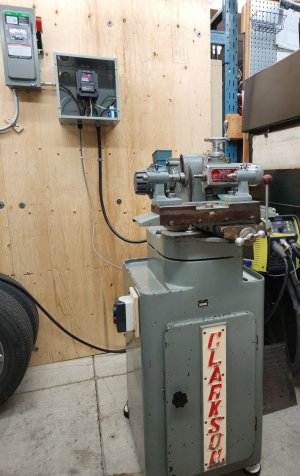
Clarkson Mk2 Tool and Cutter Grinder
- Thread starter thestelster
- Start date
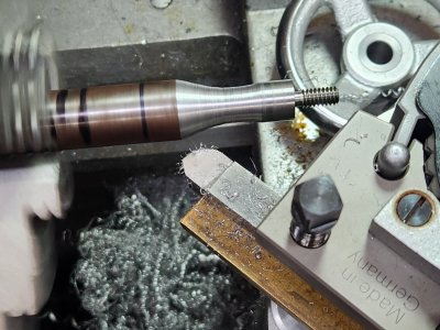
Since the bearings and races looked pretty good, and after @RobinHood post, I decided to just clean, lube and reinstall the spindle. I decided to just use grease, Shell Gadus S2 V100-2 (NLGI 2, Lithium grease, 100cSt viscosity).
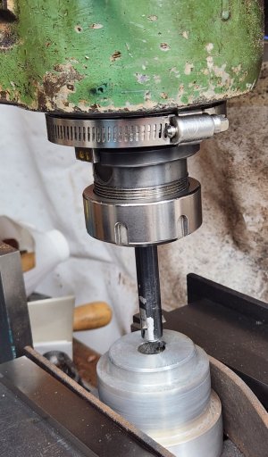
I slowly tightened the preload nut until the spindle would not rotate, and then backed it off a smidgen. The spindle turned freely with resistance - due to the grease. I then went to install the motor pulley, but it didn't have a key slot. It had the set screw bite into the key way of the old motor. This won't do. And since I don't have broaches, or a shaper, or a slotting attachment, I went old school. I put the pulley in the milling machine, and used a boring bar with a 3/16" hss bit I ground. Indicated center, put a band clamp around the mill spindle and column to prevent rotation, and using the quill for the stroke, took 0.005" passes until I got to the proper depth. The pulley is aluminium so it went quickly.
I slowly tightened the preload nut until the spindle would not rotate, and then backed it off a smidgen. The spindle turned freely with resistance - due to the grease. I then went to install the motor pulley, but it didn't have a key slot. It had the set screw bite into the key way of the old motor. This won't do. And since I don't have broaches, or a shaper, or a slotting attachment, I went old school. I put the pulley in the milling machine, and used a boring bar with a 3/16" hss bit I ground. Indicated center, put a band clamp around the mill spindle and column to prevent rotation, and using the quill for the stroke, took 0.005" passes until I got to the proper depth. The pulley is aluminium so it went quickly.
Attachments
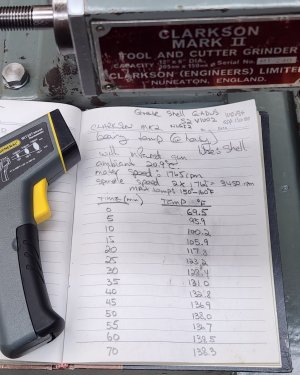
This morning I decided to run the spindle and try to measure bearing temperatures. Spindle speed is 3450 rpm. After a bunch of reading to find what the optimal operating bearing temperature is supposed to be. Apparently on several sources, says to keep the temperatures below 150-160°F.
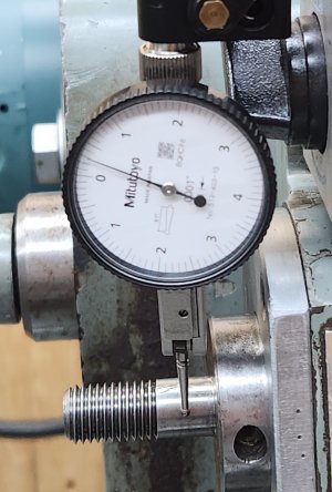
So using an infrared gun, I took measurements at the end of spindle housing opposite the bearing location. Every 5 minutes. After more than an hour, the temperatures seemed to stabilize at 138°F. So I think we're good. Have a look at the picture, it has the results of the test.
I now have to clean up the table, and do a bunch of other minor stuff and we should be ready to grind our first cutter. Probably woodruff key cutters.
Attachments
RobinHood
Ultra Member
@thestelster , nothing like broaching in the mill. Works great for one-off jobs like yours.
Glad cleaning, re-packing and running in the bearings worked for you.
I did the oil conversion before I discovered this grease from SKF ( not affiliated) (was actually looking for Klüber bearing grease, which is $$$$$s):

 www.skf.com
I have been running it in the spindle of the surface grinder. It seems to hold up very well.
I might go back to greased bearings on my Clarkson some day…
Did you end up measuring the spindle runout after your refurb?
Glad cleaning, re-packing and running in the bearings worked for you.
I did the oil conversion before I discovered this grease from SKF ( not affiliated) (was actually looking for Klüber bearing grease, which is $$$$$s):
SKF
I have been running it in the spindle of the surface grinder. It seems to hold up very well.
I might go back to greased bearings on my Clarkson some day…
Did you end up measuring the spindle runout after your refurb?
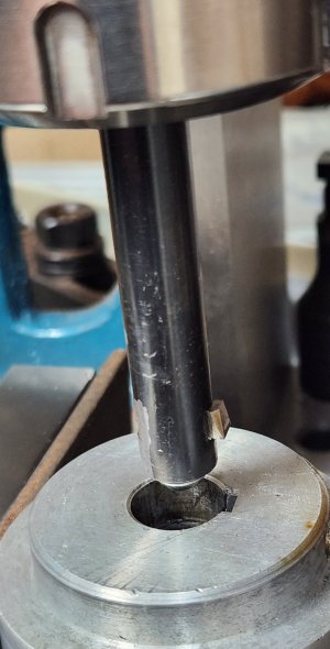
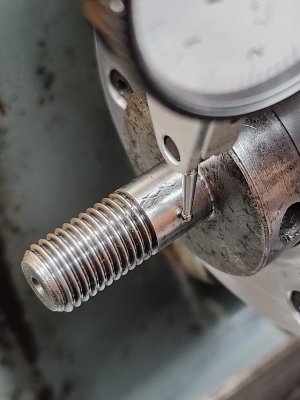
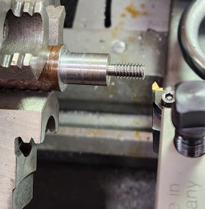
I should have measured after the test. But right now, cold (room temp), runout is 3 tenths. But have a look at the second picture. Somebody in it's past history grabbed the spindle with a pair of pliers , so measuring it can be misleading. And there is half a tenth of play, where before it was 2.5 thou' play.
, so measuring it can be misleading. And there is half a tenth of play, where before it was 2.5 thou' play.Attachments
It's not as if I did much. Just thoroughly cleaned, lubed, and tightened up the pre-load nut.
Somebody in it's past history grabbed the spindle with a pair of pliers
Usually marks like that make the needle bounce, which can be ignored because you know it can't be runout.
Yes, but given enough force, the surrounding area is raised, so you get an oblong shape. It really doesn't matter, once the wheel is trued everything is good.Usually marks like that make the needle bounce, which can be ignored because you know it can't be runout.
Yes, but given enough force, the surrounding area is raised, so you get an oblong shape. It really doesn't matter, once the wheel is trued everything is good.
I didn't know you were talking about marks that big... In that case, I'd prolly try to true off of 3 points and cross my fingers down wind.
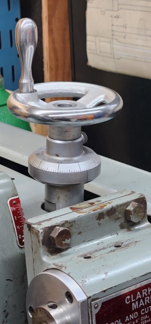
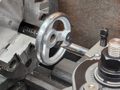
When I got the Clarkson, it didn't have the ball crank for raising and lowering the spindle head. So I ordered a cast iron hand wheel from Ebay in the US. But the hub was threaded for a size larger than the diameter of the elevation spindle. So I bored it out, made a steel plug and press fit it in. Then drilled and reamed to 0.500". I also had to install a set screw. And, the hand wheel didn't come with a handle. So I made one from some piece of steel lying in the bin.
Attachments
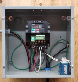
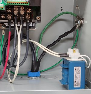
Today, I installed the DC link choke. Here is the explanation of what it is:
MTE’s DC LINK CHOKES, also referred to as DC line chokes or inductor chokes, are an economical means of filtering and controlling the DC bus voltage and current in a variable speed drive/inverter. They help reduce AC input line current harmonic distortion while absorbing DC bus voltage spikes. Link Chokes add protection and filtering but should not be considered a direct alternative to AC input or output reactors.
MTE’s DC LINK CHOKES offer the advantage of maximizing the circuit inductance for power quality reasons, but without causing an AC input line voltage drop. Link Chokes can be used individually, typically on the positive DC bus, or in pairs with one each on both the positive and negative bus. When two DC Link Chokes are used on the bus, the inductance is additive. You will need twice as much inductance on the DC bus as used on the AC input (per phase) to accomplish the same performance experienced with AC input reactors. For best performance combine the use of both an AC input reactor and a DC Link Choke.
Attachments
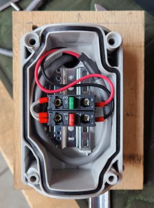
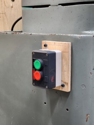
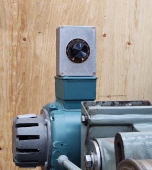
Today I installed the on/off push button switch.
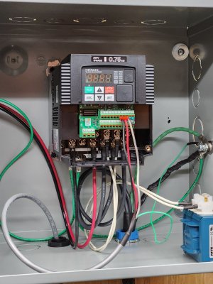
I'll be using the VFD to vary the spindle speeds, depending on which grinding wheel I'll be using. The motor to spindle pully ratio is around 2:1, but I used the laser gun to determine actual spindle speed at 60hz. It is 3685 rpm. My VFD, and I'm sure others as well, has a function where it will use the output frequency and multiply it by any constant. So, since my spindle speed is 3685 rpm@ 60hz, the ratio is 61.42. When I use that number as the constant, I can now see on the VFD display the rpm of the spindle at any frequency. Easy peasy! No need for rotary magnetic sensors. Of course this only works at one given gear or pully ratio. I can't fully utilize this method effectively on the milling machine or lathe since I'm always changing gearing.
I'll be using the VFD to vary the spindle speeds, depending on which grinding wheel I'll be using. The motor to spindle pully ratio is around 2:1, but I used the laser gun to determine actual spindle speed at 60hz. It is 3685 rpm. My VFD, and I'm sure others as well, has a function where it will use the output frequency and multiply it by any constant. So, since my spindle speed is 3685 rpm@ 60hz, the ratio is 61.42. When I use that number as the constant, I can now see on the VFD display the rpm of the spindle at any frequency. Easy peasy! No need for rotary magnetic sensors. Of course this only works at one given gear or pully ratio. I can't fully utilize this method effectively on the milling machine or lathe since I'm always changing gearing.
Attachments

My VFD, and I'm sure others as well, has a function where it will use the output frequency and multiply it by any constant.
Personally, I wanna see frequency on the VFD and RPM on the DRO or a separate dedicated rpm display.
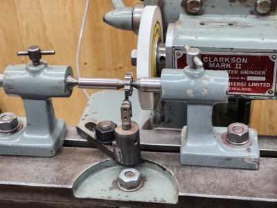
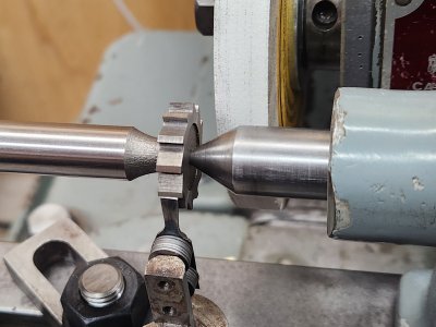
Well, it took a while to set up the toothrest, and wheel height, and a method to true the wheel, but finally, my first sharpening!!
Just a badly worn woodruff key cutter, but it worked out ok.
Still a lot of things to figure out.
I'm in the process of making a wheel guard. Thank you to @RobinHood for providing me pictures of his Clarkson guard as reference.
Just a badly worn woodruff key cutter, but it worked out ok.
Still a lot of things to figure out.
I'm in the process of making a wheel guard. Thank you to @RobinHood for providing me pictures of his Clarkson guard as reference.
Attachments
I'm still playing hooky from work ....no wonder I'm so poor!! (No thanks to you guys!)
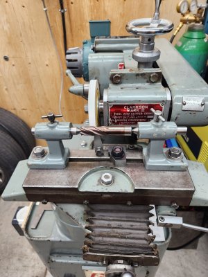
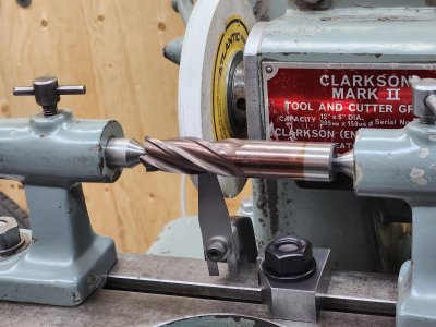
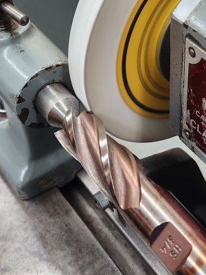
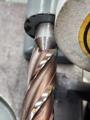
Decided to sharpen an endmill's flutes. 3/4"HSS. I have a ton of dull carbide endmills that need sharpening, but I should learn on HSS before investing in diamond wheels.
Turned out great. Definitely a lot of finess is required and a lot of time setting up. I also had to make a table stop for when I get to the end (top) of the flute, and a toolrest.
Attachments
You know.....the Tool & Cutter grinder has to be the most difficult machine to set up and use! I read you generally need 8,000hrs of experience for apprenticeship! I believe it.
Using the milling machine: high school
The lathe: college
The T&C grinder: PhD.
So many set ups, and tooling, and multiple methodologies. And there's very little information available.
Using the milling machine: high school
The lathe: college
The T&C grinder: PhD.
So many set ups, and tooling, and multiple methodologies. And there's very little information available.
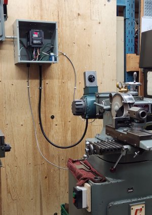
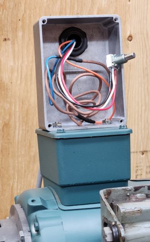
I installed a potentiometer so now I can adjust the speed of the grinder depending on which wheel I'm using without punching buttons on the VFD. For instance:
-6" straight ALOx wheel: 3700rpm
-4" cup ALOx wheel: 5,300rpm
-6" straight diamond: 2,150rpm
-3.75" cup diamond: 3,400rpm
I can set the display on the VFD to show me spindle speed as I adjust the potentiometer. I've set the max frequency in the VFD to 100Hz, so the dial on the pot corresponds with the frequency.
The pulley on the spindle gives me about a 2x increase over motor speed. And this motor's max spindle speed is 6,000rpm!!
The motor also has two thermostat wires (J-brown) which I connected to the VFD so if it goes past a certain temp the VFD will shut the motor down.
So now, all the electrical is done.
Attachments
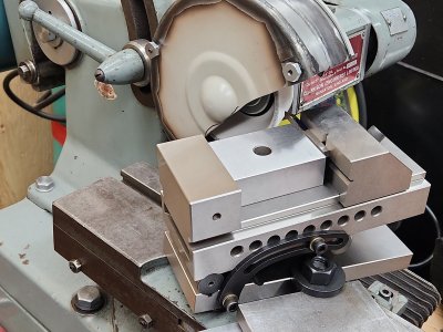
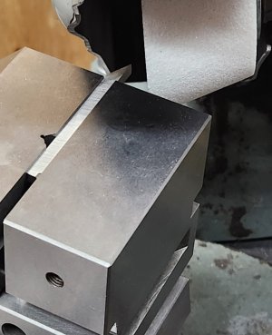
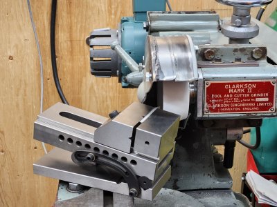
I've done a couple little jobs on the Clarkson, and everytime I want to do something on it I have to make something first to support or hold the part that needs ground.
I need to make hold downs to secure a precision vise on to the grinder table. I didn't have time for that, so I improvised by using a large washer, t-bolt and nut.
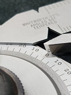
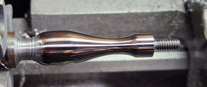
I have to make a part (extractor pawl) for an old (1914) Westley Richards single barrel shotgun. The part which I have to make has a threaded section. The thread profile is BSF (British Standard Fine) 3/16"-32. The thread angle is 55°. I have a 55° carbide threading insert, but it's for much larger pitches, and I don't have that size threading die.
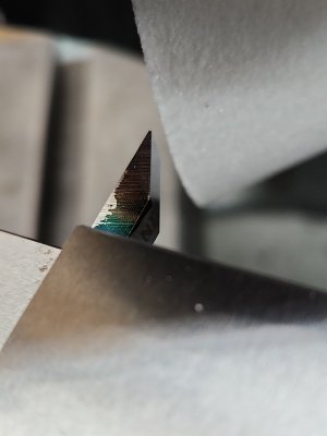
Ok, let's grind up a piece of 1/4" HSS tool blank. I roughed it out first on the bench grinder, and then used the Clarkson.
Set the sine vise to 27.5° (half of 55°) with a protractor to the table. Raised the vise with gauge blocks to give me 8° of flank clearance. Ground the one side, then repositioned the vise to do the other side flipped the tool bit upside down, and ground that side.
I need to make hold downs to secure a precision vise on to the grinder table. I didn't have time for that, so I improvised by using a large washer, t-bolt and nut.
I have to make a part (extractor pawl) for an old (1914) Westley Richards single barrel shotgun. The part which I have to make has a threaded section. The thread profile is BSF (British Standard Fine) 3/16"-32. The thread angle is 55°. I have a 55° carbide threading insert, but it's for much larger pitches, and I don't have that size threading die.
Ok, let's grind up a piece of 1/4" HSS tool blank. I roughed it out first on the bench grinder, and then used the Clarkson.
Set the sine vise to 27.5° (half of 55°) with a protractor to the table. Raised the vise with gauge blocks to give me 8° of flank clearance. Ground the one side, then repositioned the vise to do the other side flipped the tool bit upside down, and ground that side.