• Scam Alert. Members are reminded to NOT send money to buy anything. Don't buy things remote and have it shipped - go get it yourself, pay in person, and take your equipment with you. Scammers have burned people on this forum. Urgency, secrecy, excuses, selling for friend, newish members, FUD, are RED FLAGS. A video conference call is not adequate assurance. Face to face interactions are required. Please report suspicions to the forum admins. Stay Safe - anyone can get scammed.

Carriage Stop w/indicator

Susquatch

Ultra Member
Administrator
Moderator
Premium Member
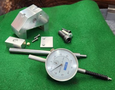
In case you need a micrometer barrel mechanism to use in a stop and didn't want to dismantle a good micrometer ....I thought these might be good (and cheap). And there are several similar choices.

Really nice find! I've had exactly that problem in the past.

No idea of the quality but it can't be that hard to make something like this that would work just fine within a thou or two.
 

thestelster

Ultra Member
Premium Member
Ok. Pretty well done.

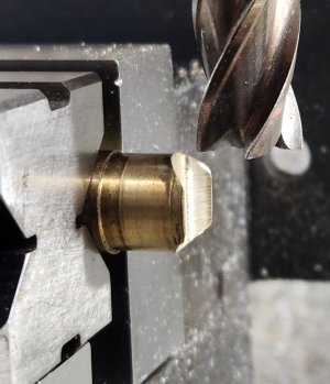
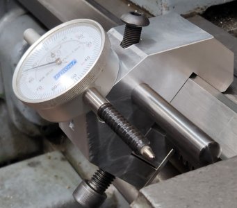
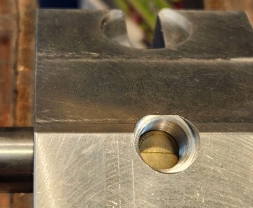
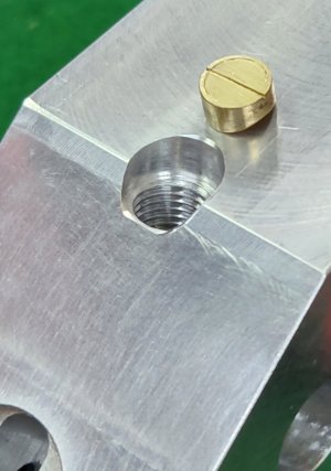
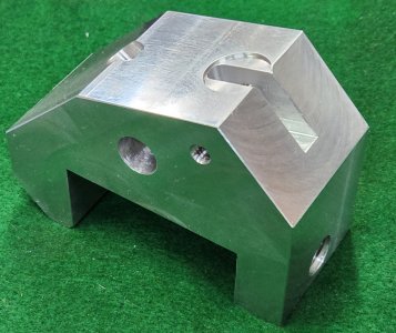
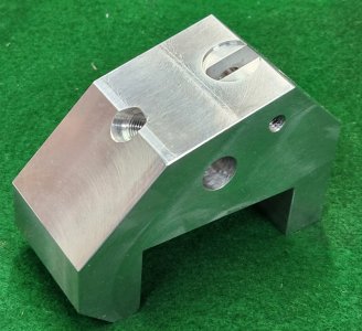
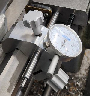
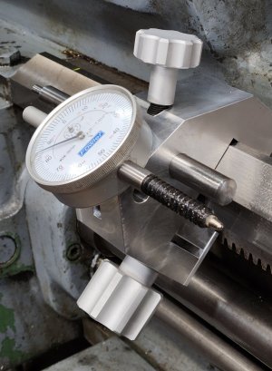
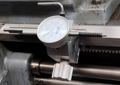
In the previous iterations, the stop rod had a flat on it so a screw would tighten onto it to secure it in place. I didn't like that idea, so I made a little brass button shaped to the contour of the rod, (1/2" diam.) With the rod a tight sliding fit into its recess, and using 3/8"-24 bolt, it provides a lot of tension.

The only additions will be handles so I dont have to use hex keys, and I don't want to use knobs.
 

Attachments

  • 20230222_153252.jpg
    20230222_153252.jpg
    861.1 KB · Views: 24
  • 20230222_153325.jpg
    20230222_153325.jpg
    639.8 KB · Views: 20
  • 20230222_153332.jpg
    20230222_153332.jpg
    461.9 KB · Views: 20
  • 20230222_153607.jpg
    20230222_153607.jpg
    242.8 KB · Views: 22
  • 20230222_153858.jpg
    20230222_153858.jpg
    359.8 KB · Views: 21
  • 20230222_155043.jpg
    20230222_155043.jpg
    562.6 KB · Views: 20
  • 20230222_155101.jpg
    20230222_155101.jpg
    243 KB · Views: 20
  • 20230222_155151.jpg
    20230222_155151.jpg
    270.5 KB · Views: 23
  • 20230222_140056.jpg
    20230222_140056.jpg
    309.1 KB · Views: 23

Susquatch

Ultra Member
Administrator
Moderator
Premium Member
Hey Sir Stelster, can you please expand on the indicator attachment? Looks like a pin through the back ear. How is that all held together such that it doesn't wiggle around.
 

thestelster

Ultra Member
Premium Member
Hey Sir Stelster, can you please expand on the indicator attachment? Looks like a pin through the back ear. How is that all held together such that it doesn't wiggle around.
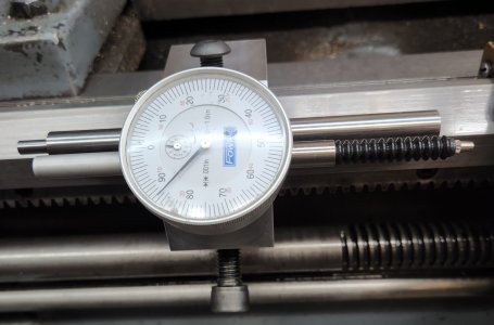
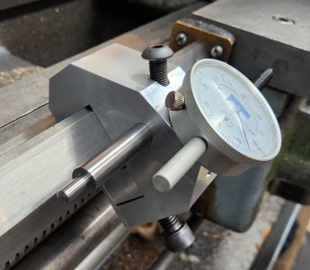
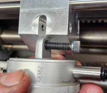
The left side of the unit is threaded. The right side has a hole 3/8" so that the head of the 1/4"-20 SHCS goes right through, and the bolt head butts up against the indicator lug. The inletting is a tight fit, so that there is no play.
 

Attachments

  • 20230222_172145.jpg
    20230222_172145.jpg
    353 KB · Views: 12
  • 20230222_172306.jpg
    20230222_172306.jpg
    290 KB · Views: 11
When I get a chance I think I am going to gratuitously steal your design and make one or better yet two of these for myself......... But, if it's okay with you, I probably won't be brave enough to show my baboon butt rendition. :p
 

thestelster

Ultra Member
Premium Member
When I get a chance I think I am going to gratuitously steal your design and make one or better yet two of these for myself......... But, if it's okay with you, I probably won't be brave enough to show my baboon butt rendition. :p
By all means! I would think that's what this forum is about, helping one another. In fact that should be everyones credo in life.
 

thestelster

Ultra Member
Premium Member
Ok, I think I'm finished with this project, until I decide I'm not!

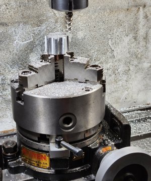
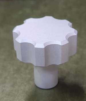
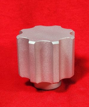
I wasn't sure if I wanted to use levers or knobs. Fluted or knurled. I temporarily used shortened allen keys onto the SHCS's, but the bottom one's arm was positioning my hand close to the lead screw, so I decided against a lever design. And to keep some continuity, decided to make the other part a knob as well. They seem to have good proportions which allows me to easily put plenty of force to tighten or release.

I was considering knurling, but I think the flutes would afford a better grip.
 

Attachments

  • 20230304_135203.jpg
    20230304_135203.jpg
    835.7 KB · Views: 28
  • 20230304_142444.jpg
    20230304_142444.jpg
    498.7 KB · Views: 27
  • 20230304_170532.jpg
    20230304_170532.jpg
    263 KB · Views: 27
  • 20230305_134947.jpg
    20230305_134947.jpg
    222 KB · Views: 29
  • 20230305_152543.jpg
    20230305_152543.jpg
    369.2 KB · Views: 29
  • 20230305_153044.jpg
    20230305_153044.jpg
    392 KB · Views: 32

thestelster

Ultra Member
Premium Member
I like the flutes better too.

How did you do the chamfer?
I chamfered the body of the knob when I turned it on the lathe.

Plunged down with an end mill on the milling machine, indexing 45degrees with the rotary table to do the flutes, 8 of them.

And then plunged down with a 45° chamfer tool until the two chamfers met.

Cleaned up the rough edges, then bead blasted.
 

Susquatch

Ultra Member
Administrator
Moderator
Premium Member
And then plunged down with a 45° chamfer tool until the two chamfers met.

I see. I assumed that's what you prolly did but the precise match with the lathe chamfer seemed too good to be done that way.

In case you don't recognize it, that was a compliment to your skill!

Beautiful job. I really like the chamferred fluting.
 

thestelster

Ultra Member
Premium Member
I see. I assumed that's what you prolly did but the precise match with the lathe chamfer seemed too good to be done that way.

In case you don't recognize it, that was a compliment to your skill!

Beautiful job. I really like the chamferred fluting.
Thank you.
 

Susquatch

Ultra Member
Administrator
Moderator
Premium Member
Two more questions for you @thestelster.

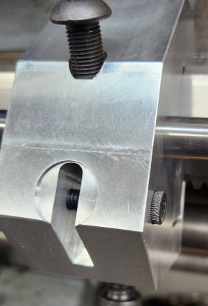
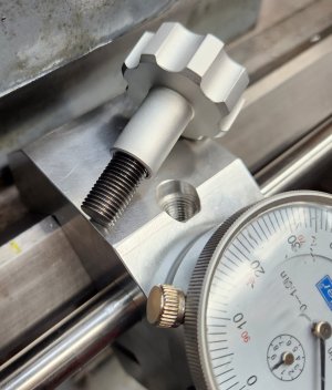
What is the Stepped Section (see arrow on photo) at the end of the stop rod for?

Why didn't you make a flat bottom recess for the screw so it doesn't tighten against an angled surface (see circle on photo)? Does that screw pivot in some way that we can't see?

Lastly, how is the indicator held in place?

20230305_153044~2.jpg
 

thestelster

Ultra Member
Premium Member
Two more questions for you @thestelster.

What is the Stepped Section (see arrow on photo) at the end of the stop rod for?

Why didn't you make a flat bottom recess for the screw so it doesn't tighten against an angled surface (see circle on photo)? Does that screw pivot in some way that we can't see?

Lastly, how is the indicator held in place?

View attachment 31701
Haha. That rod was originally for my dial indicator magnetic base, and that stepped section held the Starrett snug which held a DI. I'll cut that rod down once I determine the maximum length I need.

The threaded section of the knob tightens down on a brass piece inside the hole which pushes on the stop rod. If you go to the previous page in my post you'll see the set-up, as well as how the indicator is held in place.

As to the recessed hole, I wasn't sure exactly how the angles and dimensions were going to turn out until I actually machined the block of aluminium (since I don't have any CAD type software), so everything was by the seat of the pants. I might modify it at a later date to make it more anesthetically pleasing, but it's not a priority at the moment
 

Attachments

  • 20230306_100145.jpg
    20230306_100145.jpg
    350 KB · Views: 4

Susquatch

Ultra Member
Administrator
Moderator
Premium Member
As to the recessed hole, I wasn't sure exactly how the angles and dimensions were going to turn out...... I might modify it at a later date to make it more anesthetically pleasing, but it's not a priority at the moment

Ah yes. My brain fart. The Knob doesn't tighten down against the block so the angle doesn't matter at all except for looks. The internal screw tightens against the stop rod. If it were mine, I'd prolly never get to it.


Haha. That rod was originally for my dial indicator magnetic base, and that stepped section held the Starrett snug which held a DI. I'll cut that rod down once I determine the maximum length I need.

Gotcha. Might want to just cut the small section off and leave the rest. Someday you might want to use a longer dial indicator and need to reach further out.

as well as how the indicator is held in place.

Even looking again, I didn't see it.

20230222_172145.jpg

Then I read the post again. It was not obvious that the SH cap screw goes all the way in and bears against the indicator ear. But I see it now! Very nice! Very innovative too. I guess it would not have occurred to me to do it that way because I didn't know that all the ear dimensions are standard. Are you sure they are or are you just gunna modify as appropriate if not?
 

Susquatch

Ultra Member
Administrator
Moderator
Premium Member
As to the recessed hole, I wasn't sure exactly how the angles and dimensions were going to turn out...... I might modify it at a later date to make it more anesthetically pleasing, but it's not a priority at the moment

Ah yes. My brain fart. The Knob doesn't tighten down against the block so the angle doesn't matter at all except for looks. The internal screw tightens against the stop rod. If it were mine, I'd prolly never get to it.


Haha. That rod was originally for my dial indicator magnetic base, and that stepped section held the Starrett snug which held a DI. I'll cut that rod down once I determine the maximum length I need.

Gotcha. Might want to just cut the small section off and leave the rest. Someday you might want to use a longer dial indicator and need to reach further out.

as well as how the indicator is held in place.

Even looking again, I didn't see it.

View attachment 31714

Then I read the post again. It was not obvious that the SH cap screw all the way in and bears against the indicator ear. But I see it now! Very nice! Very innovative too. I guess it would not have occurred to me to do it that way because I didn't know that all the ear dimensions are standard. Are you sure they are or are you just gunna modify as appropriate if not?

How about making the slot a bit wider to accommodate a thin hardened washer? It would be a bit fiddly to get the washer lined up with the screw but it would eliminate any detrimental effect of tightening the small head of the screw against the indicator ear. Or maybe something like you did on the other two screws with a bigger screw hole and large steel bushing in front of the head of the cap screw to bear on the indicator tab.....
 

thestelster

Ultra Member
Premium Member
How about making the slot a bit wider to accommodate a thin hardened washer? It would be a bit fiddly to get the washer lined up with the screw but it would eliminate any detrimental effect of tightening the small head of the screw against the indicator ear.
Yes, that's easy enough to do. Though, if I'm not going go to remove the indicator, it won't have any detrimental effect on the ear of the indicator. But for sure if/when I go to use a good quality DI, I will make that small mod.
 

Susquatch

Ultra Member
Administrator
Moderator
Premium Member
Yes, that's easy enough to do. Though, if I'm not going go to remove the indicator, it won't have any detrimental effect on the ear of the indicator. But for sure if/when I go to use a good quality DI, I will make that small mod.

Thought for sure you would prefer the sleeve approach..... LOL!

I think I'm moving a new lathe stop up the priority list for the time my bride let's me go to the barn for extended periods.

I really like your design Sir Stelster. It's clearly superior to anything else I have seen so far. ;)
 

thestelster

Ultra Member
Premium Member
Thought for sure you would prefer the sleeve approach..... LOL!

I think I'm moving a new lathe stop up the priority list for the time my bride let's me go to the barn for extended periods.

I really like your design Sir Stelster. It's clearly superior to anything else I have seen so far. ;)
Yeah, the sleeve is easier to do. And it keeps the slot with minimal clearance.

I don't think the design is that great, but it works quite well. But, thank you.
 

Susquatch

Ultra Member
Administrator
Moderator
Premium Member
Hey @thestelster! I was tidying up a bit and spotted this!

20230309_180553.jpg

I knew I'd seen something like your screw Knob before! This one is a bit different from yours and might be easier to make because the chamfer doesn't need to meet any other machining edges.

Ya, I know this one has some machining marks on it. It came that way.....

By the way, this particular adjustment screw is really cool in some not so obvious ways.

It's the rear height adjustment on my competition shooting rest.

If you look closely, you might notice that is has a double lead thread on it. This provides a much faster movement for large adjustments.

What you can't see is a second thread internal to the screw with a very fine single lead thread. The combination provides both course and fine height adjustments at the range. It is a really cool idea.
 
Top