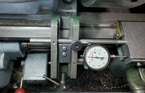
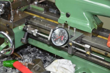
I've been using the same make shift carriage stop for over 25 years. It consists of an old cheap machine vise with the hard jaws removed, and a v-slot machined the length of the movable jaw. On the side, I drilled, tapped, and installed a socket head cap screw. I would move the stop wherever I wanted and lock it in place. So let's say I just faced-off a part in the chuck, and I wanted to make a shoulder 0.500" back. Without moving the carriage, I would put a 0.500" end mill shank (or adjustable or fixed parallel, or whatever thickness required) between the carriage and the stop bolt, and tighten the vice. Then proceed to make my shoulder. It was always a pain to adjust parallels to the dimension you needed. I have also modified that little vice to accept a dial indicator which is extremely useful when doing internal threads. So I decided to combine the two features. Its rough, but seems to work, and is a prototype for a better looking one in the future. Right now it has a fake Starrett 1", but I think I'll get a 2" dial indicator. So now I can face off a part, retract the cutter, move the carriage stop to zero on the carriage, advance the carriage to the dimension I need, push to stop rod in place and lock it in.
-
Scam Alert. Members are reminded to NOT send money to buy anything. Don't buy things remote and have it shipped - go get it yourself, pay in person, and take your equipment with you. Scammers have burned people on this forum. Urgency, secrecy, excuses, selling for friend, newish members, FUD, are RED FLAGS. A video conference call is not adequate assurance. Face to face interactions are required. Please report suspicions to the forum admins. Stay Safe - anyone can get scammed.
You are using an out of date browser. It may not display this or other websites correctly.
You should upgrade or use an alternative browser.
You should upgrade or use an alternative browser.
Carriage Stop w/indicator
- Thread starter thestelster
- Start date
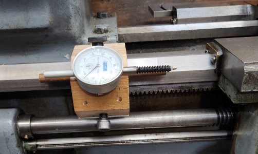
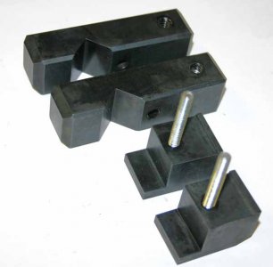
I decided to make an improved version of my carriage stop. Prototyped using a piece of 4x4 lumber, and some bits and pieces. The old one worked perfectly fine, but aesthethically.... baboon butt ugly!
I'll use it like this for a while before I make it out of aluminium or steel.
I'll use it like this for a while before I make it out of aluminium or steel.
Attachments
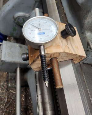
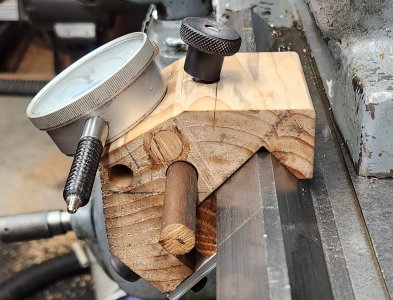
The combo stop & indicator on the same base is a neat idea. I like the angle you have on the gauge, its visible.
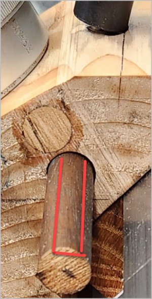
Seems to me my V1 had a retention screw like yours & I even milled milled a flat for the the contact. But I think I was still getting creep even just kissing it. So V2 I substituted with big threaded adjustment screw retained with thin knurled nuts on either end of bar. While loose you can micro adjust the setting with the knob, then just lock the thin nuts down on either side. It stays put. If you are going to make one stop I recommend making a second at same time. I use it on the opposite side of carriage like when you are turning between 2 hard stop positions. Also the spring loaded style of detent handles are good for keeping them at a preferred position or out of the way.
Seems to me my V1 had a retention screw like yours & I even milled milled a flat for the the contact. But I think I was still getting creep even just kissing it. So V2 I substituted with big threaded adjustment screw retained with thin knurled nuts on either end of bar. While loose you can micro adjust the setting with the knob, then just lock the thin nuts down on either side. It stays put. If you are going to make one stop I recommend making a second at same time. I use it on the opposite side of carriage like when you are turning between 2 hard stop positions. Also the spring loaded style of detent handles are good for keeping them at a preferred position or out of the way.
Attachments
baboon butt ugly
LOL! Ugly has just hit a new low.
But it can get worse...... I hope my bride never puts a mirror on the bottom of our toilet lid.....
Hi Peter, that's one of the advantages of having an indicator, you'll know immediately if there's any creep in the stop rod. Won't help you if the whole carriage stop unit moves though!The combo stop & indicator on the same base is a neat idea. I like the angle you have on the gauge, its visible.
Seems to me my V1 had a retention screw like yours & I even milled milled a flat for the the contact. But I think I was still getting creep even just kissing it. So V2 I substituted with big threaded adjustment screw retained with thin knurled nuts on either end of bar. While loose you can micro adjust the setting with the knob, then just lock the thin nuts down on either side. It stays put. If you are going to make one stop I recommend making a second at same time. I use it on the opposite side of carriage like when you are turning between 2 hard stop positions. Also the spring loaded style of detent handles are good for keeping them at a preferred position or out of the way.
I was considering a threaded rod with nuts, but I like the ability to quickly lengthen or shorten the stop rod.
Yes, I do plan on using levers instead of knobs.
And I can always use my version1 on the right side of the carriage when I need to.
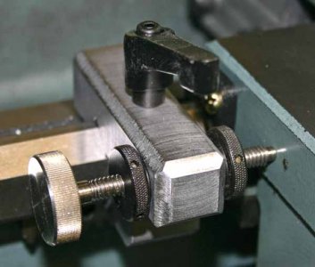
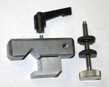
The picture below shows my Myford carriage stop.
When machining short pieces on the Myford the carriage is very near the end of the bed so I positioned the left stop to the right of the carriage. The stop rod attaches to the threading dial pivot. The stop is secured to the rod with a split cotter. A Myford bed is flat rather than prismatic so a clamp with brass insert attaches the stop to the bed. The SHCS were replaced with proper handles after the photo was taken.
When machining short pieces on the Myford the carriage is very near the end of the bed so I positioned the left stop to the right of the carriage. The stop rod attaches to the threading dial pivot. The stop is secured to the rod with a split cotter. A Myford bed is flat rather than prismatic so a clamp with brass insert attaches the stop to the bed. The SHCS were replaced with proper handles after the photo was taken.
Attachments
Last edited:
The picture below shows my Myford carriage stop.
When machining short pieces on the Myford the carriage is very near the end of the bed so I positioned the left stop to the right of the carriage. The stop rod attaches to the threading dial pivot.
Looks like someone has a 1/4-26 BSF tap..... BTW, I didn't see a thread gauge on any of the plates in the other thread for that!
")
OK, I like the idea. I have been carefully creeping up to an indicated number with my stop that clamps to the ways (ahead or behind the carriage) but I have been thinking I need to make something like you have done for more consistent work. Project #42-1000, after the DROs.
D
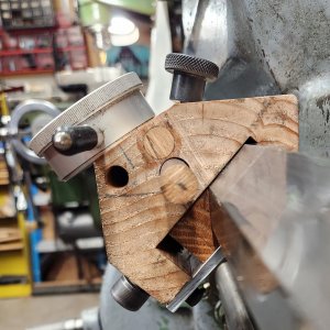
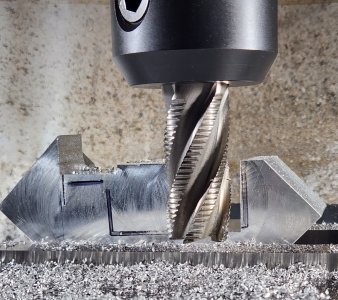
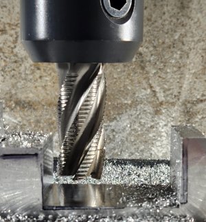
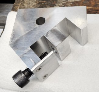
I couldnt leave it alone. Decided to start making the real thing. Aluminium. Using a 1" diameter HSS roughing endmill.
Started slotting: 0.150" depth of cut steps @1800rpm
Once I was at my depth, 1.125" then side milled at 0.100" cuts at 1800rpm. I don't have power feed for y-axis, but had to use two hands and went fast but keeping the current draw between 5-6amps, (as per what the VFD displayed).
Started slotting: 0.150" depth of cut steps @1800rpm
Once I was at my depth, 1.125" then side milled at 0.100" cuts at 1800rpm. I don't have power feed for y-axis, but had to use two hands and went fast but keeping the current draw between 5-6amps, (as per what the VFD displayed).
Attachments
Matt-Aburg
Ultra Member
Nice job. I need to make something like this. I will add it too the To-do list...I couldnt leave it alone. Decided to start making the real thing. Aluminium. Using a 1" diameter HSS roughing endmill.
Started slotting: 0.150" depth of cut steps @1800rpm
Once I was at my depth, 1.125" then side milled at 0.100" cuts at 1800rpm. I don't have power feed for y-axis, but had to use two hands and went fast but keeping the current draw between 5-6amps, (as per what the VFD displayed).
One thing is for sure. Baboons are neat looking creatures when they are sitting down !!
Man, you don't mess around when you decide to do something do you!
Hey @thestelster, do those cap screws just push that block against the bottom of the ways to hold the holder in place?
Hey @thestelster, do those cap screws just push that block against the bottom of the ways to hold the holder in place?
It's a single 1/2"-13 SHCS, for now, but I'd like to use a lever, perhaps the style that @PeterT mentioned.Man, you don't mess around when you decide to do something do you!
Hey @thestelster, do those cap screws just push that block against the bottom of the ways to hold the holder in place?
It's a single 1/2"-13 SHCS, for now, but I'd like to use a lever, perhaps the style that @PeterT mentioned.
I'm trying to understand how the clamping system works. Does the screw push that block against the bottom of the ways to hold the holder in place? And if so, what holds the block in place?
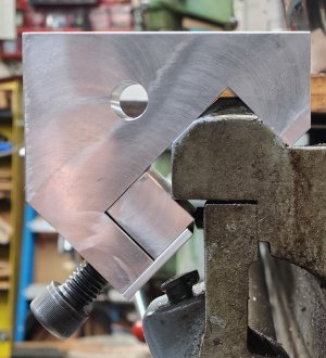
It's virtually just a small toolmakers vice. The moveable jaw is just held in place with the recessed hole and the thin shelf.
When is the last time someone told you that you are amazing?
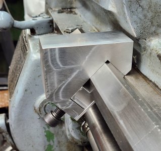
Yup, I think you are amazing! I'm gunna call you Sir Stelster from now on. That photo at the far end was a perfect way to show the install. I must have looked at 30 lathe stops before this and I've never seen anyone show it that way. But it's sooooo obviously superior.
Your second photo is perfect too. It shows the hole I didn't see before.
Your analogy to a tool makers vise is also perfect.
Yup, you are amazing Sir Stelster!
So why is the way at that end of your lathe so badly worn? I've never seen that before either. Usually, the end looks new.
Haha, yeah...no.When is the last time someone told you that you are amazing?
Yup, I think you are amazing! I'm gunna call you Sir Stelster from now on. That photo at the far end was a perfect way to show the install. I must have looked at 30 lathe stops before this and I've never seen anyone show it that way. But it's sooooo obviously superior.
Your second photo is perfect too. It shows the hole I didn't see before.
Your analogy to a tool makers vise is also perfect.
Yup, you are amazing Sir Stelster!
So why is the way at that end of your lathe so badly worn? I've never seen that before either. Usually, the end looks new.
It's not worn. Its 30+years of dirt and grime embedded into the paint.
I's not worn. Its 30+years of dirt and grime embedded into the paint.
Ahhh I see said the blind man! Took me a while, but I see it now.
I've been planning a new stop for a few years now. Thanks to you, I'm thinking I'll use the tailstock end to lay it out.
I'm watching this project of yours very closely...... The bar is high! No pressure..... Hahahaha!
Where did you get that accordion indicator cover from?
The indicator is a Fowler X-Proof which came with the dust cover. And they do offer the cover as a replacement part.Ahhh I see said the blind man! Took me a while, but I see it now.
I've been planning a new stop for a few years now. Thanks to you, I'm thinking I'll use the tailstock end to lay it out.
I'm watching this project of yours very closely...... The bar is high! No pressure..... Hahahaha!
Where did you get that accordion indicator cover from?
I was specifically looking for an indicator like that to keep dust and swarf off the rod. Unfortunately the crystal is plastic, so hot shavings melt onto it.
Unfortunately the crystal is plastic, so hot shavings melt onto it.
Sounds like your stop needs a glass shield on it Sir Stelster!
In case you need a micrometer barrel mechanism to use in a stop and didn't want to dismantle a good micrometer ....I thought these might be good (and cheap). And there are several similar choices.
C$ 5.33 48%OFF | Silver Range 0-13MM Round Needle Plat Type Measure Tool Knurled Adjustment Knob Micrometer Head Measurement Rotation Smooth
C$ 5.33 48%OFF | Silver Range 0-13MM Round Needle Plat Type Measure Tool Knurled Adjustment Knob Micrometer Head Measurement Rotation Smooth