-
Scam Alert. Members are reminded to NOT send money to buy anything. Don't buy things remote and have it shipped - go get it yourself, pay in person, and take your equipment with you. Scammers have burned people on this forum. Urgency, secrecy, excuses, selling for friend, newish members, FUD, are RED FLAGS. A video conference call is not adequate assurance. Face to face interactions are required. Please report suspicions to the forum admins. Stay Safe - anyone can get scammed.
-
Several Regions have held meetups already, but others are being planned or are evaluating the interest. The Calgary Area Meetup is set for Saturday July 12th at 10am. The signup thread is here! Arbutus has also explored interest in a Fraser Valley meetup but it seems members either missed his thread or had other plans. Let him know if you are interested in a meetup later in the year by posting here! Slowpoke is trying to pull together an Ottawa area meetup later this summer. No date has been selected yet, so let him know if you are interested here! We are not aware of any other meetups being planned this year. If you are interested in doing something in your area, let everyone know and make it happen! Meetups are a great way to make new machining friends and get hands on help in your area. Don’t be shy, sign up and come, or plan your own meetup!
You are using an out of date browser. It may not display this or other websites correctly.
You should upgrade or use an alternative browser.
You should upgrade or use an alternative browser.
Cambridge - machinist newb
- Thread starter ThirtyOneDriver
- Start date
Tom Kitta
Ultra Member
Another thing I missed dropping off the thread like I did....... There is no T-slot. Gunna have to re-read the whole thread I think.
Yes, the thing is held with a bolt. There is not enough, imho to cut a real T-lot in there / it would make things a bit too flexible - at least on designs I seen.
I don't know how much you can remove from bottom of TP without adversely affecting the action. You probably said but is it wedge or plunger?
Wedge
ThirtyOneDriver
Johnathan (John)
Ok, I've read this thread from beginning to end. It's been around the proverbial horn (of Africa) more than once.
Yes, it's a bolt. No T-slot. Thanks @Tom Kitta . I agree with you. I don't think cutting a T-slot would be easy or advisable for @ThirtyOneDriver. I assume the divot on the side of the base of the bolt is for a dowel or lock screw to keep it aligned and stop it from turning.
After giving this some real good thought based on all the info here I've arrived at the view that:
Adapting to the old pin is mostly an attempt to be able to use the old tool post without removing the compound and also to solve the size difference between the old and new post bolts.
I don't think cutting the old compound down is a good idea because of the reduced stiffness and strength.
I don't think making a new compound is a good idea either because of the required precision associated with the way compounds are normally used. That's a project for a few years down the road.
It is my opinion that it's better to use the new tool post as is with a new bolt to make it fit the existing system. The new bolt would be the same size as the old bolt except longer. A custom sleeve would adapt the old diameter to the bigger bore of the BXA tool post. Both the new bolt and the sleeve are great projects for a new machinist.
This does not solve the tool height problem. But not all the tool holders are too high. To solve that issue, I'd simply machine whatever is needed off the bottom of the ones that are too high and be done with the issue for a few years. Might also have to use smaller tools in those few cases where it's needed (eg 3/8 instead of 1/2).
Keep in mind that adapting a bigger bolt to the smaller one does not increase its strength. In fact it is probably much weaker than the original because the cross sectional area of the remaining steel in the threaded tube is smaller than the cross section of the original bolt. Also, any part is only as strong as its weakest link - which is either the original bolt or the tubular section of the new one. A sleeve at least maintains the full strength of the original bolt.
Last but not least, you could drill out the compound to take a bigger bolt and skip the sleeve without losing the ability to use the old one because the bolt end would still serve as a centering locator in the bottom of the compound.
If you REALLY REALLY feel it's necessary, you could cut a little (AS LITTLE AS POSSIBLE TO MAKE IT WORK) off the top of the compound. Nobody ever said it had to be all or nothing. Try to do it in a way that preserves the ability to use the old tool post.
That's my thinking for whatever it's worth. Oh ya, and HAVE FUN!
I'm avoiding cutting the tool post
Cutting anything off the bottom of the tool post accomplishes nothing anyway. Cutting a little off the top of the compound does help but that's a far worse solution in terms of resale. However, if you keep what you cut off of the compound to a minimum, nobody will notice or care.
What is your worst case tool holder?
Last edited:
ThirtyOneDriver
Johnathan (John)
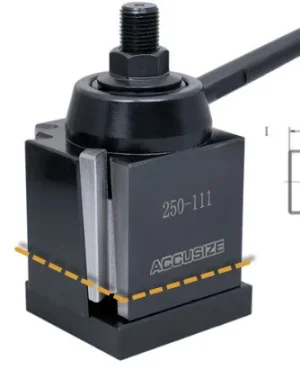
Worst case/the highest from base to cutting edge is the silver parting tool w/ the insert. It measures out to 1.195" using the micrometer - it's in a 250-202T tool meaning that the slot in the tool holder has been cut larger - that material comes off of the bottom (where you can read ACCUSIZE).

If I followed @Dabbler's instructions properly (my method of measurement is post #70), there currently is 1.1355" of gap from the top of the tool slide (compound) to the lathe center height.
Milling 0.060" off the top of the OEM tool slide (compound) is becoming pretty attractive @Susquatch.
If I followed @Dabbler's instructions properly (my method of measurement is post #70), there currently is 1.1355" of gap from the top of the tool slide (compound) to the lathe center height.
Milling 0.060" off the top of the OEM tool slide (compound) is becoming pretty attractive @Susquatch.
If I followed @Dabbler's instructions properly (my method of measurement is post #70), there currently is 1.1355" of gap from the top of the tool slide (compound) to the lathe center height.
Milling 0.060" off the top of the OEM tool slide (compound) is becoming pretty attractive @Susquatch.
First off, @Dabbler doesn't give bad advice - just the best anyone can do with whatever info he is given. If you gave him good info, I'd follow his advice if I were you. I'm not going to waste any of my time checking what he said. He will be right.
Second, 60 thou is nothing. Like I said before, nobody else will notice or care.
Third is more of an opinion.... That's a pretty beefy cutoff tool for your lathe. Too big if you ask me. I'd be seriously thinking about dumping that one and getting a smaller one if I were you. But if you really want to keep it, I'd wager a coffee or a beer that you will eventually end up turning it upside down and parting in reverse...... Which will eliminate your height constraint. As an added incentive, I'll even give you whatever you paid for it (and the holder).
Regardless, go ahead and take 60 thou off. Easy peasy to do, and seems like a no-brainer to me too!
I love the conversations being had - I'm absorbing as much as I can and every post is teaching/inspiring me.
The finish isn't the greatest, actually, I'd consider it pretty horrible, but I'm using the tools I have. When I looked up the RPM through an app (instead of going in the house and grabbing the bible) it suggested somewhere around 3000... the CX 709 can go to 1650... I have the CX 709"x" w/ the faulty/undersized motor... I can only turn 850... w/ the cheap BB 3/8" tooling...
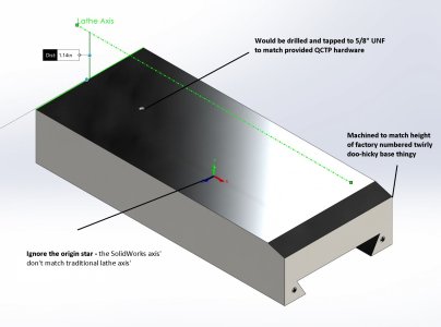
I stopped to check the fitment when I was getting ready to turn down the other end and cut (w/ a die... threading using the machine is beyond my skill level right now) the 5/8" UNF threads when something didn't work quite right. I don't remember how/where I got the M10x1.5 number from; IIRC a 3/8"-16 nut didn't thread on so I assumed the chinese/taiwan made machine was likely metric - I should have invested more time into confirming. Oh well, I get more practice.
I can't claim to be particularly skilled as a machinist but I think I might be able to offer some advice from my experience on your CRS part finish. What I see in the discussion forums says that insert tooling isn't the best thing to use to get a good (or decent for me, LOL!) finish on CRS (but does fantastic on aluminum!) and that nicely prepared HSS will do better. Actually, I only recently got into insert tooling, I spent years working with with HSS and brazed carbide tooling and I'm still climbing the steep learning curve.
Anyhow, after seeing the advice to use HSS I looked a little closer at what I was doing and experimented a bit and my finish improved. In the machining books there are recommended rake angles etc, but the thing that caught my eye was the recommendation to make the cutting edge as sharp and smooth as possible - and have more than a small rad on the end of the tool (when looking down on it). I've ground the tool then and as a finish, smooth/polish the ground faces of the tool so the material slides across the surface and at the cutting edge and doesn't give it as much of a chance to stick & gum up the faces and ruin the part finish. As I see it described, CRS is a rather gummy material that tends to, well, be gummy and draw the tool in and not cut nicely like aluminum so a sharp, smooth tool is a good tactic. I also use a cutting fluid, my favorite for this & hard materials is called Jokish HDS400.
I've just recently gotten up the courage to try and cut some threads and once you've decided to do it, it's not especially hard but still requires standard technique which you'll find in many references and thinking through what you're doing before hand. In my case I came at it cautiously and actually did the cutting by hand using a hand crank in the headstock of the Myford. That meant I had full control of how far I traveled with the cutter before withdrawing to make another pass. It has worked out great so far. It also helps that I have a quick change gearbox on my Super 7 to get the pitch set up and I have acquired "cheater" change gears that let me do (almost) perfect metric pitch with my imperial QC box. Bottom line, try it by hand first then graduate to powered threading.
BTW, I'm enjoying looking through the photos, especially the race cars....
D

ThirtyOneDriver
Johnathan (John)
@Susquatch - I do have smaller parting tools, but I may take you up on your offer - we'll work something out.
@Tecnico - I think I need to give HSS more consideration because of the speeds I'm limited to... it's not like I don't have enough tool holders and using the HSS seems like it would develop more understanding of the effects of cutting edges. I have a ton more pics of racecars; I worked on CASCAR Sportsman/Super Series, NASCAR Canadian Tire Series and NASCAR Pintys Series cars (at least one car per season, most of the time for part-time outfits) for 18 seasons continuously and have worked on a variety of chassis ranging from "pure stock" four cylinders through to limited late models - I've really been focused on improving the tooling/equipment in the shop so that I can build/setup cars at a higher standard. I've been avoiding pictures that fully identify me so that I don't need to be embarrassed about my mistakes (and therefore more transparent).
@Tecnico - I think I need to give HSS more consideration because of the speeds I'm limited to... it's not like I don't have enough tool holders and using the HSS seems like it would develop more understanding of the effects of cutting edges. I have a ton more pics of racecars; I worked on CASCAR Sportsman/Super Series, NASCAR Canadian Tire Series and NASCAR Pintys Series cars (at least one car per season, most of the time for part-time outfits) for 18 seasons continuously and have worked on a variety of chassis ranging from "pure stock" four cylinders through to limited late models - I've really been focused on improving the tooling/equipment in the shop so that I can build/setup cars at a higher standard. I've been avoiding pictures that fully identify me so that I don't need to be embarrassed about my mistakes (and therefore more transparent).
ThirtyOneDriver
Johnathan (John)
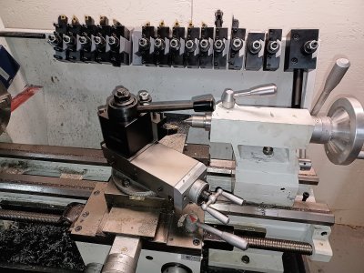
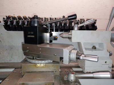
I was able to get a hand from a forum member yesterday to modify my OEM compound/tool slide - this is just a mock-up and I still need to make a threaded pin to secure the QCTP and some other small details.
As seen in the photos, I now have enough clearance for my tooling and will be able to adjust most easily using the BXA tool holders.
Thank you everyone for helping me throughout the brainstorming and planning stages of this project and thank you directly to the member that provided the assistance.
As seen in the photos, I now have enough clearance for my tooling and will be able to adjust most easily using the BXA tool holders.
Thank you everyone for helping me throughout the brainstorming and planning stages of this project and thank you directly to the member that provided the assistance.
Attachments
I was able to get a hand from a forum member yesterday to modify my OEM compound/tool slide
Not going to share which forum member came to the rescue?
ThirtyOneDriver
Johnathan (John)
Not going to share which forum member came to the rescue?
Bet he was big hairy and ugly.......
As seen in the photos, I now have enough clearance for my tooling and will be able to adjust most easily using the BXA tool holders
Looks great assembled like that even if it is still only a mockup. That's a great way to show how much clearance you have now too. Can't wait till you turn your first part!
ThirtyOneDriver
Johnathan (John)
I came across an idea that should be added to the list of things to do - it's a tubing notcher setup using the lathe instead of the milling machine like I've been using.
It appears that it's a vise setup on the cross slide(?) - the items in red are the accessories that are being sold by the company... I think they make a dedicated motor/collet/machine but IIRC it's about $2500 and I think I could get my lathe (maybe not mine, but a lathe) to work similarly.
I was exposed to the magic of VFDs yesterday and that's something I'd like to explore more - an oil change for my CX 709"x" is on the horizon and if that doesn't help it spin up to 1650 I'll explore a motor/VFD setup for the future.
I came across an idea that should be added to the list of things to do - it's a tubing notcher setup using the lathe instead of the milling machine like I've been using.View attachment 20176
It appears that it's a vise setup on the cross slide(?) - the items in red are the accessories that are being sold by the company... I think they make a dedicated motor/collet/machine but IIRC it's about $2500 and I think I could get my lathe (maybe not mine, but a lathe) to work similarly.
I was exposed to the magic of VFDs yesterday and that's something I'd like to explore more - an oil change for my CX 709"x" is on the horizon and if that doesn't help it spin up to 1650 I'll explore a motor/VFD setup for the future.
The two parts in the photo look like a vise stop and a cross slide stop. Therefore I'm guessing that the setup is designed to do repetitive notching of parts for something like a fence or railing or whatever....
To me, that looks like a really nifty way to machine the side of some tubing stock in a lathe for someone who doesn't have a mill. But I can't immediately see why someone who has a mill would want to do that on a lathe.
Can you post a few photos or drawings of what you are trying to notch and what the notches would look like?
ThirtyOneDriver
Johnathan (John)
@Susquatch - roll cage tubing; every joint has different angles, some are really close to bends, some have compound angles (airplane speak, pitch, yaw and roll) and some have a second or more tubes that intersect together that need taken into consideration when fish mouthing/notching the tubes. It's easier to explain visually/with several examples.
I have done it a variety of ways as I built tooling and experience - the main tubing size I use is 1 3/4" so toilet roll tubing has worked (may have needed slit open and taped, long time ago) - cut the tubing as a mock-up joint and transfer to steel tubing and use whatever is available to cut away material to match... that's the basic idea however one needs to go about it.
Here's what I've been using recently - it worked well for any straight tube as I'm still getting comfortable with clamping things to t-slot table.

Some tools built on the 3D printer to make things easier.


An example of what's been notched that I happen to have - I don't take many pics when I'm working.

I have done it a variety of ways as I built tooling and experience - the main tubing size I use is 1 3/4" so toilet roll tubing has worked (may have needed slit open and taped, long time ago) - cut the tubing as a mock-up joint and transfer to steel tubing and use whatever is available to cut away material to match... that's the basic idea however one needs to go about it.
Here's what I've been using recently - it worked well for any straight tube as I'm still getting comfortable with clamping things to t-slot table.
Some tools built on the 3D printer to make things easier.
An example of what's been notched that I happen to have - I don't take many pics when I'm working.