• Scam Alert. Members are reminded to NOT send money to buy anything. Don't buy things remote and have it shipped - go get it yourself, pay in person, and take your equipment with you. Scammers have burned people on this forum. Urgency, secrecy, excuses, selling for friend, newish members, FUD, are RED FLAGS. A video conference call is not adequate assurance. Face to face interactions are required. Please report suspicions to the forum admins. Stay Safe - anyone can get scammed.

Cambridge - machinist newb

deleted_user

Super User
@YYCHM I actually was trying to tell you the dovetail angle remains the same but the distance between and the depth of the dovetails varies in an AXA, BXA and CXA. I have one of all 3 tool posts in my shop now.

Thanks for clarifying how the posts are different. I should have been more specific in my post, I am usually more pedantic and specific.
 

Susquatch

Ultra Member
Administrator
Moderator
Premium Member
I understand the mental block. I don't have that particular block but I have plenty of my own.

@Chicken lights was here over the weekend & pointed out one of mine. "Whether you think you can or think you can't, you are right.". I think I can't weld so I can't. But he thinks I can if I just lose the bad mindset.

Not to worry about being an Askhole. Within limits, a wise man changes his mind often. Plus, I think we all get info and then take the time needed to process it. On top of that the process of collecting sufficient quantities the darn required monetary pieces of paper has a nasty way of adding more delays.

And here is another option:

Keep the BXA tool post for someday or even to play with.

I'll buy all (or at least some) of your tool holders provided the price is competitive - therefore no returns required. I am expecting my high speed spindle motor (aka future tool post grinder) some time today and I plan to modify a BXA tool holder to hold it. That plus I never have enough tool holders...... :D
 

PeterT

Ultra Member
Premium Member
@ThirtyOneDriver can you post the link corresponding to pic in post #39. They show a methodology to measure toolholders in order to pick the correct catalog part. But I'm hoping to extract the 'official' dovetail dimensions from that, which they don't show in the jpeg
 

ThirtyOneDriver

Johnathan (John)
Warning: this is going to be long and detailed w/ many pictures - there are notes on the majority of pictures but I will try to caption them so less reading is required.

I will do a second post immediately following this one w/ QCTP measurements... this is mainly an inventory of tool holders and tools.

250-201 holders w/ 5/8" tools
Inked20220113_111318_LI.jpg
250-201 holders w/ 3/8" tools
20220113_111328.jpg
Other 250 holders (250-202T w/ 3/4" parting tool, 250-207 parting tool that I need to order the insert for - bar(?) style?, 250-204 boring bar tool holder for 3/4 and 1" dia along w/ the boring bar set I got to go w/ it)
20220113_111337.jpg 20220113_111408.jpg

5/8" tool height = ~ 1 3/32" (27mm)
20220113_111543.jpg 20220113_111620.jpg 20220113_111655.jpg

3/8" tool height = ~ 15/16" (~24mm)
20220113_111826.jpg 20220113_111910.jpg

Parting blades varied in height (see 5/8" tools for one) - the 3/4" version w/ the "tall" tool holder is show here
20220113_112057.jpg

Boring bar tool height (I have NO experience w/ these, so this is VERY rough... I eyeball levelled the milled face, and the tool is clamped in the end of the tool holder {see first set of photos w/ boring bar inventory if needed}) - it looks like the height comes out to around 1" which is w/in the area everything else is - common sense check says that's a good thing and what I should expect.
20220113_112210.jpg

Conclusion: for these tools to work as I have them setup, I need to be able to mount the QCTP base a minimum of 1 3/32" from the chuck axis (assumptions being made here, I'm a rocket appliance, not a rocket scientist).
 

ThirtyOneDriver

Johnathan (John)
BXA (wedge style) QCTP dimensions:
20220113_114008.jpg

What really matters... OEM tool post height in relation to chuck axis (I know for a fact that the tool is not in the chuck square - I didn't expect the dimensions to be this close to one another so I felt I was w/in a tolerable amount of precision when I did the setup).
20220113_114233.jpg 20220113_114241.jpg

Taking into consideration the tooling heights from my previous post - IF I maintain this height, my 5/8" tooling will be right at/very close to lathe c/l (<---- that's the term you guys use, right?) - the 3/8" tooling should be ~ 1/10" BELOW lather c/l. That's not a tonne but in my non-educated mind, I'm "under" which I think is the important part.

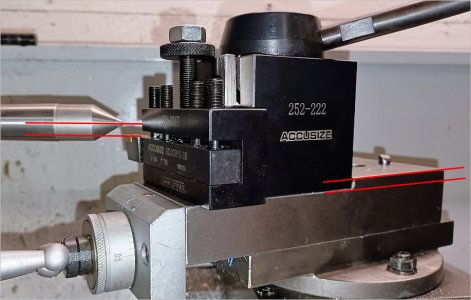
Here's photos of the tool slide for familiarization (Ali* website has ones very similar that are "AT320 76mm Center Height Metal Lathe Tool Rest" for $150).

Note that the dovetail is very imprecise and relies on (please name that chunk of metal for me, gib?) and screws to tighten it up.
20220113_114518.jpg 20220113_114546.jpg 20220113_114832.jpg 20220113_115204.jpg

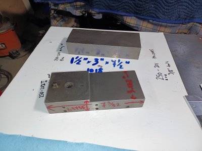
The 1018 block that I bought previously to machine a new tool slide from beside the stripped tool slide.
20220113_115805.jpg

The 60° dovetail is slightly off the OEM angle that was (scrapped?) into the tool slide - I have the t-slot tool that's just slightly undersize of what the slot would need to be (a second pass I guess).
20220113_115940.jpg 20220113_120128.jpg

This is the tooling that I have for the milling machine (CX611) so that you can guys have an understanding of capabilities (not mine of course ;) ) 20220113_121143.jpg

I took all of the information I'm currently presenting and duplicated the OEM tool slide in SolidWorks (not shown, less some details) before "adjusting" it as a hypothetical part. 
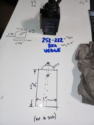
I AM GOING TO PRINT THIS PART on the 3D printer overnight as a cheap prototype (<$5). As a hypothetical part, it gave me something to create the blueprint from so I could share dimensions in an easy to follow manner.
tool slide - v2 - modified,manufactured version.JPG


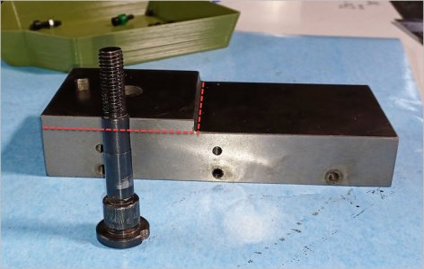
The dimensions... all of the information... culminates here... remember, the 5/8" tooling on the BXA tool holders had a height of 1.09375", the 3/8" tools were at about 15/16"...
tool slide - v2 - modified,manufactured version - drawing.JPG

Thanks for sticking w/ me this far - I haven't decided whether or not to make this part yet - I'm soliciting for your thoughts on the dimensions (is there enough material in this hypothetical part?) and what kind of impact on my lathe capabilities would it create if I decided to make this part (like negatively).

Right now, my lathe work goals mostly revolve around being able to create bushings for different applications involved w/ the stock car stuff... bushings for the spherical bearings, pucks/bushings for welding fixtures, weldable inserts for round tubing, etc. In the future I would like to create external and internal threads, bore, create internal grooves for snap rings, etc.

Everyone's help is appreciated - the effort I placed in this is a reflection of the respect I have for it.
 

Susquatch

Ultra Member
Administrator
Moderator
Premium Member
Note that the dovetail is very imprecise and relies on (please name that chunk of metal for me, gib?) and screws to tighten it up.

Yes, that chunk of metal is called a Gibb.

That is an incredible post. It's a lot to digest and a lot to comment on. You have put a lot of effort into it and that deserves a good response.

It appears as though you got a 5/8 & a 3/8 indexable tool kit and bought a tool holder for each tool. Although I like to put my commonly used tools into a permanent tool holder of their own, I probably would not have done what you did. You probably won't use all the tools and it will be a waste of tool holders. That said, you will probably find and buy a plethora of individual tools that you will want a home for. When that time comes, it will be easy to take the ones you find that you don't use that much and put them back in the box to free up a tool holder.

I bought a tool set like that a while back too. But I found that I only use one or two of the tools in it. They are simply not the best tools and I wish I had bought individual tools instead. But my needs are quite specific and perhaps others might have a different perspective on that.

The majority of the tools you have look to be ok as far as tool height is concerned. My main concerns would relate to boring bars, cutoff tools, specialty tools, and in particular those one-off tools that you will acquire one at a time in the future. It is unlikely that they will all be like the ones in the tool sets that you have.

Although the boring bar set that you have there will work, I believe they are intended to be used in a boring head on a mill - not on a lathe. I think that you will find that boring bars designed to be used on a lathe will perform a bit better than those will - especially for small holes or deep holes.

It is difficult to assess your new cross-slide design. Without a detailed side-by-side comparison. On first blush, it looks fine. How are you going to make that? And don't forget to take oil galleries into account. Lastly, if you are going to make something like that, why not put t-bolt slots into it for the future? That's a feature I wish my lathe had.

Ill re-read your post and maybe comment more in the morning.
 

ThirtyOneDriver

Johnathan (John)
@Susquatch
- I fluked into having a tool holder per tool - I bought a "set" because of the pricing and added on a number of the standard tool holders
- there was a crappier (the 3/8" tools) that I bought from BB when I bought the machines; I trusted the 'knowledgeable' staff and then bought the 5/8" when I bought the BXA - the 5/8" tools seemed like the right heft
- the boring bar set was a "didn't know what I didn't know" deal - I wanted boring bars for a part that I plan on making soon and was doing the whole Zoolander "how did they get that into the computer" deal - open to suggestions on how to choose what I should look at for boring bars - I'm not afraid to buy a boring head for the mill later... I just don't know enough about them at this point
- mock-up of the tool slide is being printed on the 3D printer right now so that I can place the items side-by-side for comparison at some point in the morning

Thanks for your input (like seriously, not factiously).
 
Last edited:

PeterT

Ultra Member
Premium Member
Not sure if this would work for you dimensionally, but could the existing part be taken down something like so, or a bit deeper for that matter & end up with the correct datum height for the tool post?
There is nothing special about the Tee-plate that is typically used on these TP's. Ultimately its a threaded hole for the center stud to engage. That's pretty much what your existing one accomplishes, just anchored differently. Actually I'd go a step further & suggest milling the big Tee slot would result in a weaker part vs. leaving it more solid-ish. The post may have to be modded to suite, but that's easy turning.

To play safe & if the price of replacement slide is reasonable $, you could sacrifice that. I can't imagine the material is hardened. Then the slot, dovetails, gib screws... all that already done.
 

Attachments

  • EDT-2022-01-13 10.40.57 PM.jpg
    EDT-2022-01-13 10.40.57 PM.jpg
    68.7 KB · Views: 5

ThirtyOneDriver

Johnathan (John)
@PeterT - I'm also thinking that if I put the t-slot in that I'm removing too much material (part of drawing it was to be able to see/imagine/measure what material I would have... I love SolidWorks in that respect). - another compound slide from (near duplicate) from AliExpress is $150 CAD... it's not a bad idea...

^ From here forward, despite pictures etc. I am not planning on having the t-slot

Here's how the mock-up went w/ the 3D printed part 'Tool Slide v2' (there's issues w/ the print, I threw this into parameters for a production run of smaller parts that's been working flawlessly for about a week)... ... just in case anyone isn't following... the 3D part is a sacrificial piece of material in this case as I figure out what I want/need.
20220114_091427.jpg 20220114_091549.jpg

The tool points are on the same x and y coordinates for their close up. The tooling is the 5/8" that I've been using as my preferred/desired baseline.

There'll be a follow-up with adjustments once I get my morning going... I can't express the gratitude I have to be able to share and get feedback.
 
Last edited:

ThirtyOneDriver

Johnathan (John)
Refined idea/design 'Tool Slide v3'... reminder that the dimension from yesterday's measurement of the 5/8" tools in the BXA tool holder was 1.09375" - this tool slide increases that dimension by 0.05" but there is "room" to increase that (tool slide v4) (someone smart could help me determine how much material to maintain between the dove tail slot on the underside and the QCTP and I can alter 3D model to that).

Tool Slide - v3.JPG Tool Slide - v3 - upside down.JPG

'Tool Slide v3' and 'Tool Slide v2' share the same 1.14" dimension from Lathe C/L to QCTP base/tool slide top surface.
 

ThirtyOneDriver

Johnathan (John)
'Tool Slide v4' increases the critical tool slide surface to lathe C/L by an additional 0.20" (now 1.29" - OEM was 1.09").
Tool Slide - v4.JPG

There looks like there's enough meat between the dovetail cut and the top surface. @PeterT - this is what the tool slide would look like if I did exactly what you described with the diagram you made... which is the same as a bunch of other, smarter (than I), individuals have also described.

My apologies for needing to work through the problem to catch up to you guys.

This is where Tool Slide v4 puts me visually... (v4 is the same height as the unused end of the tool slide)
20220114_115620.jpg 20220114_115705.jpg

My 'tallest' tool
20220114_115845.jpg

Consensus... I'm leaning towards machining the v4 tool slide from the chunk of 1018 I have (pictured in one of the earlier, longer threads).
 
Last edited:

PeterT

Ultra Member
Premium Member
So just eyeballing your picture, your cutting tool tip is residing below lathe center axis with toolholder bottomed out. So you seem to be well positioned once the toolholder is jacked up into position. That looks to be about the same distance if you were to plane off the stair bump. That looks to be about the nominal fattest toolholder shank you can accommodate. Maybe other than the bump knurler, which are not very kind to smaller lathes anyway & would be better replaced with scissor style. So what am I missing, why cant you modify the existing slide? Imean if you want to make one, I get that. But is there a dimensional reason the existing cannot be modded?

Depending on your 1018 stock size, be prepared that it might stress relieve a little bit. Best to take equal amounts off. There may be better material choices but I get that's what you have & want to try.

Re Solidworks, I'm guessing by your intro you are getting discount for military service? (bravo btw). Just curious have you heard any news that they are swapping that out for the 99$ Maker version? I've heard that's the case for EAA discount full version, will go bye-bye if it hasn't been implemented already.
 

Attachments

  • SNAG-1-14-2022 006.jpg
    SNAG-1-14-2022 006.jpg
    105.9 KB · Views: 2

ThirtyOneDriver

Johnathan (John)
@PeterT - no dimensional reasoning, more a confidence (or lack there of) issue - if I don't cut into the original, my lathe stays functional despite how long it takes me to work on it in the mill, etc. I admit bias towards machining a part and that exists because one way or another, I need to gain experience - going in straight lines seems like easy(ier) experience... ? possibly? If there's a better material to use (could make one version out of aluminum/whatever material to gain experience and have a 'back-up' plan; AND THEN machine the OEM version to match as you suggest) that would be better than 1018 I can use this somewhere else/for another project. I was in a hurry before Christmas and scrounging for supplies because I thought I'd be working on this when all the stores were closed. Wasted material/broken tooling (of course, try to avoid that) won't affect the food on my table and I see them similar to paying tuition to learn at a school... although metal costs have sky-rocketed, I still think the material cost is cheap relative to the value of the knowledge/experience (in short, I'll pay more/again to get better experience).

You're correct that I have SW through the Veteran program - I paid for the maker version for a year because COVID had jammed up my ability to meet the "proof" requirements for the Vet program; I'm not sure what the differences were of what I had and what I have now. Doubtful that SW would get rid of the Veteran program as I've been told the owner(?) is a Vet but as I re-read what you posted, it's possible they roll it back to a more basic version. I don't think I bothered registering all of the modules.
 
Last edited:

ThirtyOneDriver

Johnathan (John)
You guys challenge me with great questions/comments. @PeterT, I'm confident that I have a "full" version... I've just been using what I need to use and haven't done any exploring since I installed the 2021 version. I was surprised when I did some more digging... here's a screen shot of the add-ins.
SW.JPG
 

PeterT

Ultra Member
Premium Member
Re the slide, that's where I was wondering out loud how much a replacement part slide would cost. If it were cheap & readily available, just do the dirty deed on that. I won't speculate on either cheapness or availabiliy though. Guessing its may not be something they inventory but some of the other forums I frequent have indicated good turnaround. Maybe they have perpetual parts shipments coming & its just a matter of specifying what you want. Worth an inquiry. You may need to know that for another part in the future anyways.

Aluminum would not be a great choice IMO. I guess we've come full circle, look out 1018 here we come LOL. Not sure on your stock size but if it can be a bit wider & assist with providing more TP footprint contact, that would be a good thing. Right now with the bigger TP & compound at an angle, looks like you have unsupported overhang. Not the end of the world but if you have a clean sheet of paper, bigger is better.

Re SW, I think before the Maker version came out mid/late-2021? EAA was like the Military service promo. It was a full version no different than a paid seat, registered & installed on your machine, files stayed on your machine etc. But of course awesome price. Now they have been rolling out 99USD Maker. I believe first as a standalone offering, but also stated it will replace the EAA. I cant seem to find where I read that Military & Education as well. ie. anything other than a full license seat will only get Maker. What might be confusing matters is what you paid for full might just be matching the Maker price & renewal/reset is forthcoming. Functionally there will be some operating differences. Sorry for the tangent, this got chatted a bit in another SW/CAD post. I was just curious.

https://www.reddit.com/r/SolidWorks/comments/rvwbl4
 

ThirtyOneDriver

Johnathan (John)
So a flier came in the mail last night that reaffirmed my desire to keep the OEM tool slide unmodified... it had bigger lathes in it. There were at least three members who mentioned that I'd have the desire to upgrade - it won't happen right away, but they were correct. Keeping the original tool slide unmodified will enable me to sell the lathe "complete".

@PeterT - I have 'Tool Slide v4' printed and mocked up - the QCTP and the tool slide dimensions "match"
27461-5a9c32713cdeb703f704c19e4ff1b175.jpg
27468-cca28e96eef30721a79eca4046d6bafb.jpg

Help me follow - what's the benefit of a wider (let's say y-axis referring to the picture above/depth) tool slide? - I did notice on the mock-up that the tool holder tail hangs off of the tool slide and is unsupported (I don't think this would be an issue, but I'm open to input).
 

ThirtyOneDriver

Johnathan (John)
Another possible solution based off earlier suggestions (like the YouTube video posted); an adapter to change the OEM tool post hardware to one that will work w/ the BXA QCTP.

Seems like an easier and quicker interim solution (probably could have had it made w/ all of the work put into posting... my shop is uncomfortably cold and needs the propane reconnected and I've been getting over the virus this week) and I could break it down into smaller portions (spacer bushings instead of bore) to make it even easier.
QCTP retrofit post.JPG
... I'm still processing one solution at a time ... it's not the most efficient method but I'm still growing
 

PeterT

Ultra Member
Premium Member
This is an exaggerated sketch but just trying to depict the narrower top slide body just visually eyeing your stock relative to existing top slide. Maybe its more of a photo thing that makes it look smaller. I didn't read through all your dimensions. But anyways the unsupported remaining (white triangle) area is what I was saying ideally should be minimized. What dictates the TP block angle is you may want to have your compound set at a certain preferred angle, but your TP still needs to be close to square to the work, so the rotation is the byproduct. Hope this makes sense. If I'm way off base on the size, just ignore. Thats all I was trying to say. Ya see how all these issues kind of stack up & just getting a smaller TP kind of isn't too crazy huh? LOL
 

Attachments

  • SNAG-2022-01-15 9.44.04 AM.jpg
    SNAG-2022-01-15 9.44.04 AM.jpg
    20.9 KB · Views: 1

Susquatch

Ultra Member
Administrator
Moderator
Premium Member
..... and I've been getting over the virus this week) and....... I'm still processing one solution at a time ... it's not the most efficient method but I'm still growing

One of the symptoms of the new Omicron varient is Brain Fog. It happened to me. I could actually feel my IQ drop off the proverbial Cliff. Prolly not the best time to be analysing tool post alternatives......
 
Top