• Scam Alert. Members are reminded to NOT send money to buy anything. Don't buy things remote and have it shipped - go get it yourself, pay in person, and take your equipment with you. Scammers have burned people on this forum. Urgency, secrecy, excuses, selling for friend, newish members, FUD, are RED FLAGS. A video conference call is not adequate assurance. Face to face interactions are required. Please report suspicions to the forum admins. Stay Safe - anyone can get scammed.

Bought a diamond in the rough mill probly

justin1

Super User
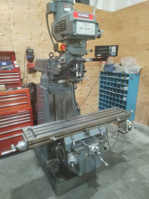
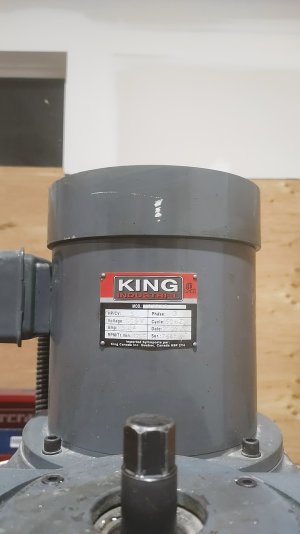
So I picked up my first mill it's a king 1050vs and for the most part seems in good condition not that old, used in low production environment and comes with dro and power feed head and table and some light abuse.

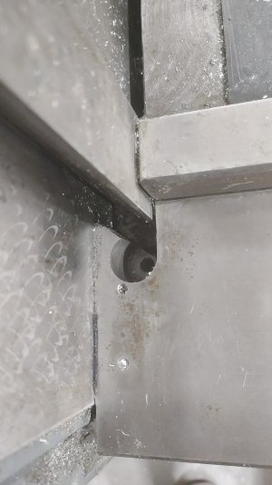
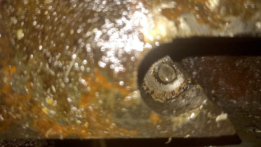
Anyways long story short the gib is stuck In the knee and they broke gib lock screw and lost the tightening screw :( and looks like an attempt to free it up has been made and was unsuccessful hopefully resulting in no real damage but I will not know untill I investigate further.

So currently looking into the various ways people have solved this issue and seems to be few different methods but this one has been highly recommended https://www.practicalmachinist.com/forum/threads/knee-stuck-gib-is-jammed.141376/

So I would like to get some input from more knowledgeable people. Maybe learn a thing or too and hopefully come out the other side not any worse off.

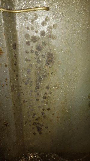
I figure if I'm gonna go threw a bigger disassembly I may aswell clean the mill and get it all happy again as it appears the shipping coating was never fully removed on some surfaces and maybe wasn't oiled as much as it could have been. So I would like advice on cleaning as well. I plan on just using kerosene and brass brush to do most cleaning.

Also wouldn't mind some input on 220v single phase to 600v 3 phase VFDs as I think I would like to go down VFD route but I'm curious what others have done with success for the 600v motors

Anyways here is some pictures for your viewing pleasure.
 

Attachments

  • IMG_20230125_215139.jpg
    IMG_20230125_215139.jpg
    407.9 KB · Views: 76
  • IMG_20230125_213012.jpg
    IMG_20230125_213012.jpg
    205.1 KB · Views: 74
  • IMG_20230125_215258.jpg
    IMG_20230125_215258.jpg
    299.8 KB · Views: 53
  • IMG_20230125_215142.jpg
    IMG_20230125_215142.jpg
    368.8 KB · Views: 54
  • IMG_20230125_213035.jpg
    IMG_20230125_213035.jpg
    145.5 KB · Views: 76
Wow.....

For some reason, I can't read the link you posted.

As a farmer, I take big stuff apart all the time. One thing I have learned is the need for patience.

I think the most important advice I can provide is to resist any temptation to do anything until you know exactly what is in there and how it all fits together. It sounds like you are already on that page but it's worth emphasizing that anyway.

Some investigation won't hurt though. Is that photo from the top or from the bottom? Can you see the Gibb and/or the Gibb channel from the opposite end? Access there might prove important in the future. If there isn't any access then have a good look at how you might provide access if needed. This is about laying out options for yourself because you might need to push the Gibb out from the other end.

I'd ask if the knee will move but that would require trying to move it and I wouldn't do that just yet. Is the knee at its far bottom end of travel? If not, you might consider rigging up some blocking so it can't move any further. I'm not suggesting any pressure, just prevent it from further movement.

Do you have a parts breakdown for the mill? If not, then try to get a manual for the closest machine you can find. Maybe several to identify differences and get closest to yours. I highly recommend the Grizzly Manuals. They seem to do a really good job compared to King and Busy Bee. Even if you can find the right King Manual, see if you can find a Grizzly mill that looks like yours and get their manual too.

I'd also begin planning a strip down of the mill. You may find it is necessary to lay the mill base and knee on the floor or even upside down. If so, you would want to remove the head, ram, and table first. So it's worth taking some time to plan that process now. But I would not do it yet, I'd just be planning for it.

My guess is that laying the base down on its back with the knee pointing up will take the most pressure off the knee ways and Gibb. So again, look at how you might accomplish that. If you do end up doing that, you might want to make a cradle for it before laying it down. Basically a piece of plywood with 2x4s screwed to it that the mill would lay on. Think field dressing a deer.

I'd also suggest looking at what special tools you might need to buy or make.

Sounds like a rewarding project. Those ways look to be in GREAT shape. If that's any indication, you might really have that gem you want!
 
This is the procedure as posted on Practical Machinist by Forrest Addy in 2007. It sounds to me like very sound instructions by someone with experience with successful repairs and failures due to this problem. I had my old 1050 mill apart to the level he suggests and it's not for the faint of heart but not really that difficult. I would do it exactly as he described.


COPIED FROM PRACTICAL MACHINIST
YES!! I've successfully salvaged seven machines in this situation and seen maybe a dozen that were botched resulting in cracked knee or column casting.

Stop. Ignore all conflicting advice especially if it seems easier. The only safe solution for a stuck knee gib is a heroic remedy.

You've described a classic stuck knee gib. You are very close to permanently damaging the machine's knee or the column. By permanently damaging I mean cracking the column or knee at the interior angle of the dovetail. Further movement of the knee or the gib in the wrong direction has to be avoided at all cost.

Tear down the machine removing the table, saddle and turret (leaving the ram and head in place if you can handle them safely assembled). Remove the elevating screw, gears, elevating shaft and gears, and internal lube fittings from the knee. The knee gib adjustors have laready been removed you say. Obtain a piece of plate about 10" wide x 3/4 or more thick by long enough to bridge the turret diameter plus 5". Use thin cardboard to protect the scraped surface from the rough plate. Drill four 9/16 holes on 2" centers along a radius to pass the turret clamping bolts through about 6" back from the front edge. Make a piece of 1/2 thick x 10" wide steel plate long enough to span from the turret to the knee. Position it to clear the gib. Fit this plate carefully so it gets good bearing between its ends and the knee and the turret plate. Do not use wood.

Assemble the plate over the turret opening and attach with the turret clamping bolts using lengths of pipe to make up the difference in bolt grip. Install the other plate between the turret face and the top of the knee where the felt wiper would go. Apply some downward force but do not try too shift the knee at this time. Merely snug up the nuts. The object of the turret face plate and the peice down the from its to keep the knee from rising with the gib as it's tested.

Lay the column on its back, blocking it with timber so it does not roll. Drill a hole in the base casting in line with the knee gib and excavate with a die grinder to pass through a punch in line with the gib. Make a 1" dia steel punch about 2 ft long and make the end a parallelogram slightly smaller than the gib. Place it in the excavated hole and position it against the small end of the gib. Bump it firmly but not vigorously with the largest hammer available. If the gib does not move it's time for heat inside the knee.

Secure a large oxy-acetylene outfit with a rosebud tip. Heat inside the knee only the whole of the casting between the dovetails. Do not heat the column. I refer to the clearance metal of the knee between the docetails and not the masses that include the dovetails. Keep the torch moving and avoid localized heating. This will expand the knee casting without harm. The expansion will release the tension on the dovetail and relax the force on the gib. Have your helper test the gib by bumping with the hammer from time to time. As the knee warms and the metal expaands sooner or later the gib will become free.

This is a job that takes hours or days to set up but only minutes to execute. It has low surgcal risk when done correctly.

Work over all parts paying close attention to the knee and its gib. clean up and inspect the divertail interior angles for inspection under magnification. Dies check for cracks. If there are cracks present there is no permanent repair possible that does not involve replacemet or welding of a major casting. A repair of a sort may be made using IronTite repair technique perpendicular to the crack plane. This keeps the crack from spreading. Google "IronTite."

Remedy all defects particularly those having to do with the gib adjustors. If the gib will not adjust correctly use a brass shim behind it to compensate for wear. Clean and reassenble in the usual way noteing condition and wear as you go unless there is cause for immediate re-scraping and reconditioning.

Any solution that involves hydraulic jacks, heavy hammering, or avoids machine disassembly may damage or complicate the fix.

Beause of the gravity of the original poster's sutuation, I ask others to not contribute to this thread unless they have actual experience as a machine tool mechanic in a remedy of this particular problem. A single lucky break or "a guy told me" does not qualify as experience.

Please forgive my arrogance but this situation warrants careful procedure. Conflicting advise will jeapordize an expensive and hard to replace machine tool.

[ 05-20-2007, 08:17 AM: Message edited by: Forrest Addy ]
 
That's a nice looking machine. It has box ways on the Y axis and dovetail ways on the Z, I don't think I've seen that before. Usually both axes are one type or the other. Looks like it has a 40 taper spindle also so it was meant to be a robust mill. Take your time with the repair and it should turn out OK.
 
Last edited:
This is the procedure as posted on Practical Machinist by Forrest Addy in 2007.

Nice to see Forrest quoted. While almost inactive now, he's been a mainstay on other forums for decades and I don't think I met anyone on the net or in person who has as much credibility and knowledge. (as well as a very helpful nature and an excellent writer). If Forrest said it, I'd pay close attention.
 
Last edited:
This is the procedure as posted on Practical Machinist by Forrest Addy in 2007. It sounds to me like very sound instructions by someone with experience with successful repairs and failures due to this problem.

Thanks for that John. I couldn't read it for some reason. I don't know Addy nor ever seen his posts before. But it sure sounds like good advice to me. It does make me feel like I wasted my time replying before though.... Oh well, I couldn't sleep anyway and what I did say didn't conflict.

I did like my deer butchering cradle better than his though...... Making the cradle and screwing the 2x4s to plywood while the mill is still standing seems wiser to me as then the cradle can't slip apart when he sets the mill down on it.

That plate arrangement sounds interesting. I hope @justin1 posts his progress. I'll be following. Who knows, maybe we can help more later on.
 
I have a king 9x42 and so far it's been a good machine. The manual is not the best, Grizzly has an much better manual for a very similar machine., part numbers will oblivious be different.
 
Ye the king manual is ok I guess. I'll look into grizzlies and see if it proves more useful as more information definitely helps.

I want to source the missing gib screws before I start the dissection and then reorganize the shop to make room for this operation.

@Susquatch don't worry I plan on taking a bunch of pictures for the forums and so I don't forget anything in the process :(

I will be following forrests instructions when I do start the repair. But I'm curious if liquid nitrogen poured down wey would work similar to heating up casting but maybe more accurate compared to heating up casting? But I'm not opposed to tiger torching area just curious
 
I used the crane to lift off the table, and cross slide as well.


Since your knee is jammed this won't help for disassembly but may be of interest when re-assembling. I used a scissor jack to support and lift the knee while I removed the knee jacking screw assembly then I put a long eye bolt down through the jack screw hole to lift the knee off with the engine crane. I balance well like this and was very manageable.


But I'm curious if liquid nitrogen poured down wey would work similar to heating up casting but maybe more accurate compared to heating up casting? But I'm not opposed to tiger torching area just curious

I bought a used set of disks a while back. It had been neglected and not greased properly. One of the wing hinge pins was frozen in place. I tried various ways to pull that pin and ended up drilling it all the way through, adding water ports to the ends to run cold water through the middle, torching the casing with the biggest rosebud I have (E3), applying a big puller in push mode, and using a slide hammer on the other end. All starting with the puller, then adding the slide hammer, then adding heat, then adding water. The water did the trick and it let go with a bang that I thought was gunna put the pin through the neighbours barn a mile away. So ya, a combination of heating and cooling works. Your biggest problem will be keeping the nitrogen where it belongs on the inside parts.

Having read Addy's post, I doubt you will need it. In fact, I'll wager a coffee you don't need heat either. Once you take the load off of everything it will probably come out on its own with a few big hammer taps on your big punch. Just go slow and methodical.

When I removed the head and ram as an assembly I did it with an engine crane. I turned the head upside down and used a long 1/2" eye bolt with the threaded end cut off, chucked in a collet as a second lift point to balance the assembly. Once it found the correct link to balance it, it cam off nicely.


When I took the head and ram off of my Bridgeport to replace the base spider, I just rotated the head around like you did, but I found the balance point using an engine levelling beam, and lifted the whole thing off with my gantry crane. It was an easy peasy job. Turned out that the spider was broken inside the base so I just replaced it instead of repairing it.

Btw, when I reviewed my first post just now, I realized my cradle instructions are misleading. You build the 2x4 & plywood cradle with the mill standing so it's easy to make it fit. Put some tape on the mill pillar for alignment. Then you put the cradle on the floor and then lay the mill base on it. Since it's pre-built to fit you don't need to worry about stuff rolling around or sliding or not fitting very well.
 
@John Conroy When I was at Modern they were doing a teardown & it looked just like that. One would think some kind of chip diversion shield like you made would be so simple & prevent so many problems down the road. Do you think this is normal undisturbed buildup just over years of use? This actually reminded me to check if there was sufficient access to stick a vacuum snorkel up in there on my 935. I'm not sure if removed the rear splash cover & retract the table, would I get partial access through the casting opening from the top? Is that the entrance path for chips to begin with?

1674760690274.webp
1674760948695.webp
 
@John Conroy When I was at Modern they were doing a teardown & it looked just like that. One would think some kind of chip diversion shield like you made would be so simple & prevent so many problems down the road. Do you think this is normal undisturbed buildup just over years of use? This actually reminded me to check if there was sufficient access to stick a vacuum snorkel up in there on my 935. I'm not sure if removed the rear splash cover & retract the table, would I get partial access through the casting opening from the top? Is that the entrance path for chips to begin with?

View attachment 30003View attachment 30006
I'm going to suggest that only happens with too much use of air to clean fine material.
 
I rarely use air only when I have to like pocket milling tiny stuff & only if I cant vacuum.
But where is it entering on example? Under the mat & in through the casting opening? That's a lot of swarf
1674762208982.webp
 
Nice to see Forrest quoted. While almost inactive now, he's been a mainstay on other forums for decades and I don't think I met anyone on the net or in person who has as much credibility and knowledge. (as well as a very helpful nature and an excellent writer). If Forrest said it, I'd pay close attention.
Especially when he says things like "Stop. Ignore all conflicting advice especially if it seems easier."
 
@John Conroy When I was at Modern they were doing a teardown & it looked just like that. One would think some kind of chip diversion shield like you made would be so simple & prevent so many problems down the road. Do you think this is normal undisturbed buildup just over years of use? This actually reminded me to check if there was sufficient access to stick a vacuum snorkel up in there on my 935. I'm not sure if removed the rear splash cover & retract the table, would I get partial access through the casting opening from the top? Is that the entrance path for chips to begin with?

View attachment 30003View attachment 30006
There were no rubber way covers on that machine when I got it. I think the chips made their way down through the sliding/layered chip shield (60 and 61 in your pic) under the cross slide due to years of neglect.
 
Out of curiosity I've emailed Donald Chen at Bergerda to see what the price (and shipping weight) for a 4.5kW 2000 RPM 220VAC AC Servo and drive. Might not be a lot different from a 220VAC to 550VAC 3 phase VFD.

You can set the speed with either a POT supplying 0-10V or PWM from an electronic module or do like I do and use step/dir for full range speed control.

Just curious.
 
I rarely use air only when I have to like pocket milling tiny stuff & only if I cant vacuum.
But where is it entering on example? Under the mat & in through the casting opening? That's a lot of swarf
View attachment 30009
I don’t know the answer but my excello had a 5 gallon buckets worth of swarf in the knee when I got it.
 
Back
Top