• Spring 2024 meetup in Calgary - date Saturday, April 20/2024. discussion Please RSVP Here to confirm and get your invitation and the location details. RSVP NOW so organizers can plan to get sufficient food etc. One week to go! More info and agenda
  • We are having email/registration problems again. Diagnosis is underway. New users sorry if you are having trouble getting registered. We are exploring different options to get registered. Contact the forum via another member or on facebook if you're stuck. Update -> we think it is fixed. Let us know if not.
  • Spring meet up in Ontario, April 6/2024. NEW LOCATION See Post #31 Discussion AND THE NEW LOCATION

Bought a diamond in the rough mill probly

Ask @phaxtris what he thinks about welding cast. Pro advice.

From what I understand there are very specialized rods that work well for stick. Otherwise I personally would go TIG with a stainless steel filler (based on my research into the subject), I have done a few small welds this way with success. Brazing with TIG or Torch is the other option. Amateur advice.
 

Susquatch

Ultra Member
Administrator
Moderator
Premium Member
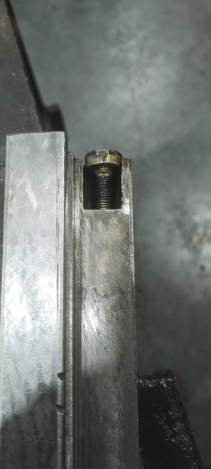
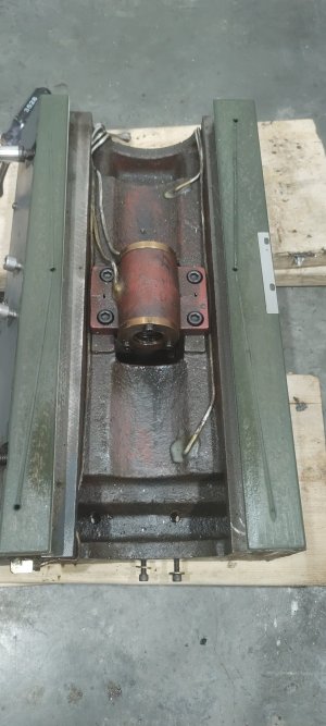
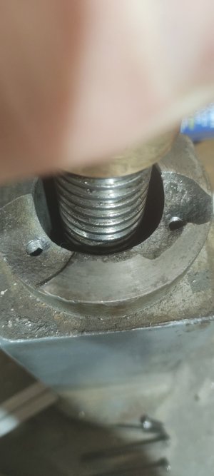
I fix broken castings like that REGULARLY on farm equipment and tractors. So I'm gunna focus on that fix for you. I'm definitely on the tap it deeper and use a longer bolt page. Don't even try to weld it.

But you might find it hard to find a long enough tap if you try to tap it after filling with epoxy. No problem! Do it before filling with epoxy!

Just tap the existing hole as deep as your regular tap will go. Then coat the longer bolt liberally with Release agent and install it. (Shoe wax works great as a release agent.) Then apply the epoxy to form threads around the bolt and fill the majority of the break with epoxy. Monitor the epoxy cure/set very closely. When it reaches a set where it is VERY DIFFICULT BUT STILL POSSIBLE to dent with your thumbnail, remove the bolt and let the epoxy finish curing for 24 hours. Don't be tempted to go back to a shorter bolt though...... Epoxy is strong, but not that strong!

An alternative to @Dabbler's suggested aluminium filled epoxy which is hard to find and often big $, is to get some steel reinforced JBWeld or even mix some regular JBWeld with some cast iron dust. Make sure the dust is clean dust though - no oily swarf.

If I was doing this, I would also apply a first layer of epoxy a little shy of the amount needed and then apply it in two stages. A first stage to fill the main break and a second stage to fit the parts so that no filing or machining is required. Just rough up the surface of the first stage before applying the second layer. This would require release agent on both the bolt and the mating casting and assembly before it cures. And again, break the bolt fit and perhaps even remove the mating casting before final cure.

I have sometimes used a temporary bolt as a locating pin by cutting off the head in order to avoid getting epoxy down in the hole before assembly as well as to help align the parts before curing.

One more tip is to use playdough or modelling clay to make a mold to contain the epoxy for the first layer. Even the heavy epoxy types flow a bit. If you remove the casting before the second layer fully cures, you can use a really sharp knife to cut away the little bit that will have squished out. Or use a die grinder to machine it away later.

The process above generates a perfect fit of the parts and also accommodates a slight shrink in the bulk of the first layer as it cures.

It's a lot easier to do than it reads. So don't be afraid of it. The results will be drop dead beautiful! You will be so proud of it that you will want to post a picture to show the world!
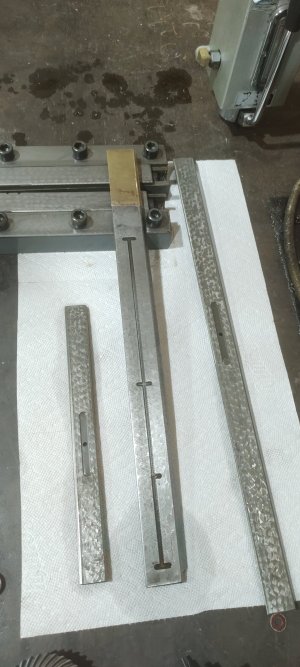
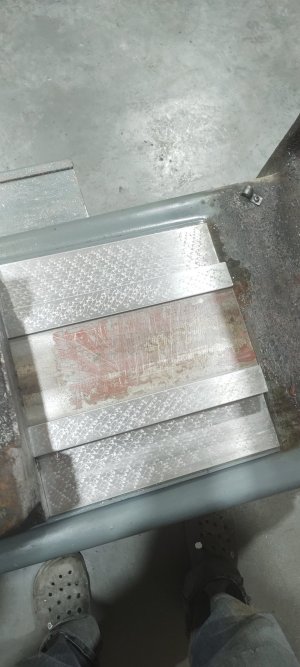
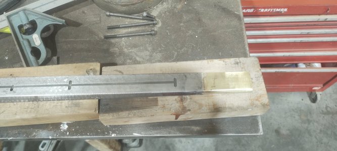
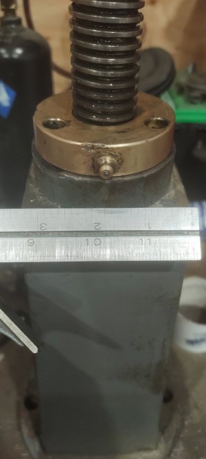
 
Last edited:

phaxtris

(Ryan)
Premium Member
Premium Member
Thanks @Degen

I can't exactly tell what is being repaired? It looks like the original holes were tapped shallow and someone over torqued and popped some of the casting off? If that's right here are my thoughts

I agree with everyone, I wouldn't even bother to weld that, your option of tapping and redrilling is a good one, least hassle

What I would probabaly do, build up those areas with braze and grind/controur/mill to the original shape, then re-drill and tap your holes, a coat of paint and no one would ever know....or just buff it up, the contrast between cast and braze looks good IMO

A guy could be confident with a braze repair lasting as long as the machine, brazing is the more traditional/prevalent method of cast repair for good reason, simple, easy, strong, and long lasting
 

Dabbler

ersatz engineer
I can't exactly tell what is being repaired? It looks like the original holes were tapped shallow and someone over torqued and popped some of the casting off? If that's right here are my thought

I figured the same thing, which is why I suggested filled epoxy.

An alternative to @Dabbler's suggested aluminium filled epoxy which is hard to find and often big $, is to get some steel reinforced JBWeld or even mix some regular JBWeld with some cast iron dust. Make sure the dust is clean dust though - no oily swarf.
oof!! Last time I had to repair a casting the aluminum filled epoxy was the cheap stuff. For the purposes of the repair, the filling is only to make the epoxy a lot less runny and provide slightly more support. Anything with a high compressive strength will work, including glass bead or other blasting media - except silica sand, which won't give you the necessary strength.
 

Proxule

Ultra Member
Ask @phaxtris what he thinks about welding cast. Pro advice.

From what I understand there are very specialized rods that work well for stick. Otherwise I personally would go TIG with a stainless steel filler (based on my research into the subject), I have done a few small welds this way with success. Brazing with TIG or Torch is the other option. Amateur advice.
Cast is most often brazed with oxy fuel or oxy propane and low fuming bronze or TIG brazed with silicone bronze or aluminum bronze.
If you desire to weld you can use stick electrodes with a nickel rod, 55% content or 99% content, If machining is required or multiple passes will be done, stick to nickel 99%

With pre and post heat and a slow cooling rate, The topic has been discussed on here several times.
I would refrain from welding, and consider brazing if you want to go down that route.

An option not used any more is to weld it with CAST IRON filler rod, With a ferro flux and VERY high heat, Not common nor taught any more. I shy away form it because of the intense heat it takes to get everything molten, Upside is its a perfect color math and identical strength.

gluck
 

Dabbler

ersatz engineer
But you might find it hard to find a long enough tap if you try to tap it after filling with epoxy. No problem! Do it before filling with epoxy!
My bolts are 3/8 NC, so any 3/8 tap will give you about 2" of threads in that instance. You are 100% right about tapping first.
 

RobinHood

Ultra Member
Premium Member
and last but not least the broken knee stand i was thinking of using some cast iron rod i have laying around to repair then re-drill holes in new locations. or other option i'm thinking of is just buying longer cap screws and fix the threads that are there and just not worry about it. as welding it could cause more issues then its worth.

Those are two broken-off SHCS I presume? If you can get them out without damaging the threads, I would just machine off that top portion so you have a flat surface for the bronze nut to sit on. Then I would make a mild steel spacer ring (the thickness of which is the same as the height of the material you took off). Drill the holes deeper and thread them. Use longer bolts and you are done.

That section of the knee support only ever sees compression (unless you decide to lift the machine by the table/knee). The nut needs to sit on there square otherwise it will bind and wear prematurely. The three screws are there to prevent the nut from turning. So the SHCS should only see shear forces and a little bit of tensile forces to keep them tight in the nut/threads.

No glueing or welding; and you can use the original holes. Would not surprise me if the nut only fits on one way - as in the hole spacing is not exactly 120*…; seen that enough times in the past.
 

justin1

Super User
Other than shipping and of course the labour to mount a different size motor, the Grizzly Motor at $300 US plus shipping (Heavy) and a VFD for anything from $150 to $500 plus shipping again.
ye seems no matter which way you cut it costs are similar is just a matter of how much work a guy wants to do to get a running machine :S i'm kinda lazy in that sense it is nice to just push one button and be done lol
From what I understand there are very specialized rods that work well for stick. Otherwise I personally would go TIG with a stainless steel filler (based on my research into the subject), I have done a few small welds this way with success. Brazing with TIG or Torch is the other option. Amateur advice.
that is correct if you want a 99% seamless cast iron look then stick welding cast is the way to go but there is a lot of risk with it. me being a welder by trade with some cast experience its just kinda fun to toss around idea I also have few different flavors of cast rod arctec makes some nice rods for cast.

Tig a very good option as well as you can use silicone bronze or 309 ss or inconel work good for cast repair depending on application. the nice thing about tig is you can really manage the heat input because you want to melt the cast enough to get surface fusion but not melt whole bunch into the filler metal. it also helps using a filler with similar expansion if you can not control the heat.

brazing is a pretty tried and true method and probably the most cost effective as well considering cast iron stick rod starts at 50$ a pound. but like every other method you can defiantly screw it up and destroy what your attempting to fix.

@Susquatch @phaxtris @Dabbler @RobinHood
I was able to weld a nut to what was left of broken bolts and extract and there is about half inch of usable thread in whats left of were the bolts broke casting, my mill is M6 cap screws they were 1" long going to replace with 1 1/2" bolts. for the repair of the knee base thing i'm probably just going to run with just the longer bolts and call it a day as there is 70% of original surface left for brass nut to sit on. but that being said i got 3-6 days to wait for a new knee spindle bearing so i may end up JB welding missing sections see how i feel once all the cleaning has been done.

An option not used any more is to weld it with CAST IRON filler rod, With a ferro flux and VERY high heat, Not common nor taught any more. I shy away form it because of the intense heat it takes to get everything molten, Upside is its a perfect color math and identical strength.
never heard of that method sounds like thermite welding with less steps pretty much. I forgot about nickel 99/aluminum bronze. would also recommend them but both are fairly pricey as well. As far as pre and post heating ye that is a very lengthy topic and very scientific. I've had good success when working on larger cast iron repairs not using heat and only running small bead 1 at a time then peening because if you can't heat up large part consistent enough and cool it off just as good its almost worse in long run on life of the iron. which on heavy equipment is dam near impossible. but the range on cast iron composition is insane some of it you can just use 7018 and it will stick...

Anyways for today's progress i didn't get whole lot done I had some running around to do. But I got the knee and column all cleaned up. I extracted 2 broken bolts out of knee stand thing and what was left of gib adjustment bolt. then chased some threads and replace the oil line I melted and last but not least I Silvaloy'd a piece of brass i had laying around to broken gib adding back the roughly 2 7/8 missing gib. I figured 15" inching of good gib should be fine I don't plan on running this mill that hard. probably.... I felt it was the less invasive way of heating up the Gib and if its good enough to hold carbide to stuff its probably strong enough to hold brass to a gib ;) then I cut off and beveled extra material and used a trusted straight edge to make sure i had no brass contacting the weys. its only purpuse is to give the locking adjustment screw somthing to push on.
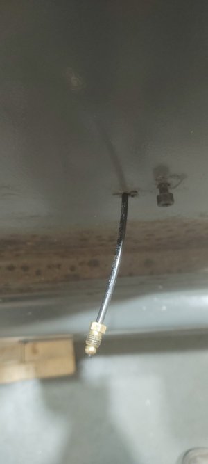
 

Attachments

  • IMG_20230130_193602995.jpg
    IMG_20230130_193602995.jpg
    113.2 KB · Views: 22
  • IMG_20230130_193614069.jpg
    IMG_20230130_193614069.jpg
    281.9 KB · Views: 20
  • IMG_20230130_193255590.jpg
    IMG_20230130_193255590.jpg
    290.7 KB · Views: 24
  • IMG_20230130_193516161.jpg
    IMG_20230130_193516161.jpg
    169.8 KB · Views: 25
Last edited:

Susquatch

Ultra Member
Administrator
Moderator
Premium Member
Anyways for today's progress i didn't get whole lot done I had some running around to do. But I got the knee and column all cleaned up. I extracted 2 broken bolts out of knee stand thing and what was left of gib adjustment bolt. then chased some threads and replace the oil line I melted and last but not least I Silvaloy'd a piece of brass i had laying around to broken gib adding back the roughly 2 7/8 missing gib. I figured 15" inching of good gib should be fine I don't plan on running this mill that hard. probably....

I think you got alot more done than I would have. Good on you!

How big is that flange and those broken pieces? I had this image in my mind of something huge but your last photo makes the whole thing look a lot smaller! Is there another chip on the left side or is that by design?

The flaking on your ways is beautiful and the very low wear suggests that your mill is in fantastic shape.
 

John Conroy

member
Premium Member
Nicely done, that gib repair should work fine. I can't think of how the top of the knee jack pedestal would get damaged like that without destroying the bronze nut. Is the nut undamaged? I assume it looks like all the other Bridgeport clone machines, like this?

Screenshot_20230131-064137_Microsoft 365 (Office).jpg Screenshot_20230131-064418_Microsoft 365 (Office).jpg
 
Last edited:

Proxule

Ultra Member
never heard of that method sounds like thermite welding with less steps pretty much.
Thermite welding in a set it and forget it route. Mainly for large industrial settings. Like train tracks or large section of non structural steel.

The cast iron FUSION welding is not taught much any more. My pops taught me and only ever seen other old timers in the saw mill use it. Its benefits are exact color match and identical strength and metal composition.
It takes a long time to produce the weld and you use a filler rod of cast iron and a suitable flux that can break up the iron oxide and silicon dioxide formed on top of the molten puddle.
You are actually casting the filler rod into the parent material. Like at the foundry.... lots of heat needed - not maybe !
Cooling time and rate is critical because the whole welded assembly or area must be heated to cast iron flowing temps. Vs. Using low fuming or silicon bronze @ 1400F

Amusingly the old generation or at least who I worked with, called nickel rods camouflage welding cast iron.

So as time passed. And metallurgy changed. And "time is money"... suitable strength can be achieved, Etc etc. Bronzes (low fuming, silicon, aluminum) took precedence.

Cast iron welding and brazing always seems to be haphazard.

Nice repair of the gib!

gluck
 

justin1

Super User
@Susquatch @John Conroy
Ye the knee stand thing isn't super big about 3 inches and I don't think the chips are by design but they will be now lol. And for the most part the bronze nut is undamaged some marring on it. And the old owner broke the nut free from base trying to use excessive force on knee handle to lift the table off the broken gib I assume they Broke the handle (it didn't come with mill) and then they tried using a pipe wrench to probly try and force the table free some more lol. So fairly luck the cap screws used to hold nut down only had about 1/4 inch of thread in cast or they probly would of destroyed the nut.

So far worse wear I found is on one side of the Y axis some corrosion damage about 6 or so inch's long lots of high spots left so in a way its kinda like flaking so more oil retention? Probly.

@Proxule

I can definitely see why the process had more or less been abandoned I couldn't imagine the cost to have someone come do a sizeable repair vs the options we have now. But ye time is money nothing gets rebuilt now a days "cheaper" to buy new companies would rather have there trades do nothing it seems then idly rebuild stuff when there is down time because the man hours cost more then the part lol.

And ye cast iron is a wild beast that is for sure, you can do the same thing multiple times and still get different results.

Also I got this style dro the X axis doesn't seem to work all the time would cleaning them real good fix that or better just to replace the 2 dro gauges they don't seem overly expensive.
 

Attachments

  • IMG_20230131_103952437.jpg
    IMG_20230131_103952437.jpg
    153.8 KB · Views: 11
  • IMG_20230131_104014186.jpg
    IMG_20230131_104014186.jpg
    175.6 KB · Views: 10
  • IMG_20230131_104057584.jpg
    IMG_20230131_104057584.jpg
    278.8 KB · Views: 9
  • IMG_20230131_103054074.jpg
    IMG_20230131_103054074.jpg
    112.9 KB · Views: 11

jcdammeyer

John
Premium Member
If it turns out the ACME flange and screw are damaged you do have another option, although a bit more complicated.
Here's a photo of my vertical post with ACME screw in bronze nut.
KneeScrew.jpg
Like the others it uses a pair of bevel gears and a horizontal shaft out the front. Cranking up and down is a pain in the butt so like many others the first thing I did on this mill was add power feed with my ELS providing the step/dir pulses.
Now I have an AC Servo on it and there's only minimal backlash but I've always wanted to change it to a ball screw. Instead of turning the ball screw I plan on fixing it to the knee and turning the ball nut instead. Here's a view of how that would work.

Original Knee Post as in the photo.
AcmeKneeAssembly.jpg
I'd replace the pipe and flange with something a bit bigger that I can weld a bracket to and then insert the assembly and the motor would sit vertically on the post.
KneeBallScrew.jpg

Here's the parts.
BallKneeAssembly.jpg
The grey pulley attaches to the charcoal ball nut which attaches to the blue hub which turns in the orange bearings that are held in the pink holder. There would be a double nut or locked nut holding the blue hub providing compression on the angular contact bearings.

As yet this is still only on the drawing board.
 

justin1

Super User
Seems kinda of complicated from what I remember when guys convert knee mills they just use a flanged ballscrew nut in lieu of the bronze nut more or less but I guess if your driving the axis from there you would want more support for sideways force. Compared to driving from the knee handle
 

jcdammeyer

John
Premium Member
Seems kinda of complicated from what I remember when guys convert knee mills they just use a flanged ballscrew nut in lieu of the bronze nut more or less but I guess if your driving the axis from there you would want more support for sideways force. Compared to driving from the knee handle
The bevel gears will always have backlash. Not an original idea. A guy in Australia did it to a mill like mine.
 

Susquatch

Ultra Member
Administrator
Moderator
Premium Member
Hey, @justin1 ,

Is this brass nut flange what screws onto your broken casting?

IMG_20230130_193516161~2.jpg

IMG_20230131_103952437~2.jpg

If so, I'm so glad you posted this. I have a MUCH better idea of what you are trying to do now. I had assumed we were talking about a huge part.

I agree that a deeper tap and longer bolt is prolly all that's required. I'd still do a single stage epoxy repair though - just so the bolts can be tightened without distorting the brass flange. Just coat the flange in shoe polish and let the epoxy set till you can't dent it then crack it all loose before it turns to rock. No need for a double layer with a part so small.

Just wondering - how do the inside threads on the brass nut look? I'd hate to have that all apart and not change it if needed.

Never saw a grease zirk on the nut before. I like that!

And look at all those filings in the threads...... :oops:

It's going to be a gorgeous mill when you are all done!
 

justin1

Super User
@Susquatch

Yes it is, and I haven't taken the nut off shaft but there isn't any play in it and it feels fine. When I clean the acme screws I'll inspect the nut closer but I'm under the impression it's perfectly fine at the moment. Ye the zirk seems like good idea then again a guy could just brush on some grease aswell acme threads are very exposed.

It will be a functional mill anyways I don't plan on doing any painting what ever cutting lube they used with mill just destroyed the paint on bottom of knee and my tiger torch also baked some of it off :)
 

Proxule

Ultra Member
Also I got this style dro the X axis doesn't seem to work all the time would cleaning them real good fix that or better just to replace the 2 dro gauges they don't seem overly expensive.

I do believe those are regular glass scales?
Some one with more exp might confirm.
When I got my scales from China - One of them had a teeny chip of the glass at the very end, So I tore it apart to file a claim.
I noticed its nothing more then a glass strip - https://www.dropros.com/images/Clean.JPG
So some alcohol or some other non aggressive solvent in there?
Same thing with the reading head, Might solve your issues before you pump more money into it,

Gluck
 

justin1

Super User
Ye not 100% sure yet on scale kinda left them alone the wiper seals are missing off then aswell so not sure what to expect gonna looking into them more see if they are a serviceable item.

Anyways update for what I got done today pretty much got everything cleaned that I wanted to do that can't be done when mill is back together. Chased some more threads and found some more evidence of abuse in my travels and blew out some oil lines. aswell as cleaned out the one shot oiler was full of all kinds of nasty then finished up by pulling the knee spindle bearing out as it was packed with aluminium chips and was crunchy asf so figured I would clean it out just in case the new sealed bearing was wrong for some reason. Didn't want the knee to get stuck agian but for a different reason... But now the only thing left is cleaning the dro scales maybe... while I wait for new bearing from Ontario once that arrives I can put everything back together :)
 

Attachments

  • IMG_20230131_140647266.jpg
    IMG_20230131_140647266.jpg
    225 KB · Views: 16
  • IMG_20230131_172500935.jpg
    IMG_20230131_172500935.jpg
    186.8 KB · Views: 15
  • IMG_20230131_172541103.jpg
    IMG_20230131_172541103.jpg
    212.7 KB · Views: 14
  • IMG_20230131_104057584.jpg
    IMG_20230131_104057584.jpg
    278.8 KB · Views: 18
  • IMG_20230131_172421852.jpg
    IMG_20230131_172421852.jpg
    297.5 KB · Views: 17
  • IMG_20230131_172655589.jpg
    IMG_20230131_172655589.jpg
    279.8 KB · Views: 16
  • IMG_20230131_173147555.jpg
    IMG_20230131_173147555.jpg
    124.7 KB · Views: 16

jcdammeyer

John
Premium Member
Ye not 100% sure yet on scale kinda left them alone the wiper seals are missing off then aswell so not sure what to expect gonna looking into them more see if they are a serviceable item.

Anyways update for what I got done today pretty much got everything cleaned that I wanted to do that can't be done when mill is back together. Chased some more threads and found some more evidence of abuse in my travels and blew out some oil lines. aswell as cleaned out the one shot oiler was full of all kinds of nasty then finished up by pulling the knee spindle bearing out as it was packed with aluminium chips and was crunchy asf so figured I would clean it out just in case the new sealed bearing was wrong for some reason. Didn't want the knee to get stuck agian but for a different reason... But now the only thing left is cleaning the dro scales maybe... while I wait for new bearing from Ontario once that arrives I can put everything back together :)
You are doing an awesome job on cleaning this all up. Very nicely done.
 
Top