The BHM - a benchtop hobbing and gear cutting machine.
This project has been brewing for a couple of years and its now in a working, but not pretty stage, so I thought I would share a few details.
Gear hobbing is a highly efficient and accurate machining process used to create teeth on gears, splines, and sprockets. The multi-toothed cutting tool, called a hob, looks somewhat like a worm or a screw with cutting edges.
Here's how it works:
The BHM is designed to produce spur, helical and bevel gears - however we must use an involute cutter and an indexed action to produce bevel, miter and crown gears using the shift & rotate method.
The machine is built from barstock, with a 16" x 16 " footprint and 20" high. It weighs approximately 150 lbs.
There are the three linear axes, Z for depth of cut, Y for the work advance through the hob and X for transverse shift to utilize all of the hob length when it becomes worn.
When cutting helical gears, the gear helix angle is set manually with a quadrant plate.
When cutting bevel gears, the work axis can be tilted to match the various bevel angles.
The hob can cut either above or below the work, with the cutting forces directed towards the chuck.
The workhead spindle and the hob spindle are very precisely synchronised to generate the correct tooth profile. The hob spindle is driven by a large NEMA 23 servomotor, geared down 3:2 and the workhead is geared down 3:1 for increased torque. When cutting, the hob runs about 120 to 200 RPM and the gear blank at approximately spindle RPM divided by the number of teeth.
Originally I had intended to use a standard CNC control board to drive the steppers and servos. However AFAIK there is no precision spindle coordination that can be controlled using g-code, so I developed a custom controller based on the Teensy 4.1, and my own software and firmware to coordinate the 5 motors. The software is a continuous development (read 'neverending") process which is the cause of my grey hair.
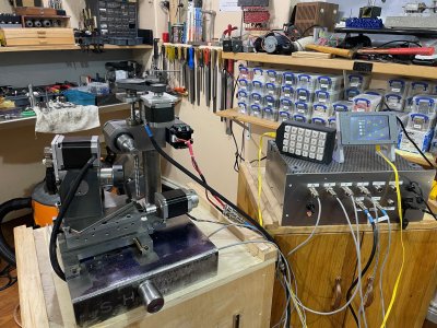
The HMI (Human Machine Interface) is an 800x480 colour touch screen, and a custom 24 key keyboard.
Here's a few pictures of the machine at this stage and some finished gears. If there's a way to upload videos, I'll post those too.


Setting the gear helix angle on the quadrant plate, and setting the tilt to zero using a 123 block


The undercarriage showing the X ballscrew and the hob helix adjustment mechanism.
The micrometer allows 1' (1 minute) adjustment.

Cutting a 60T M0.6 helical gear and a similar spur gear. Left/Right helical and a pair of spur gears made from Delrin.
Small gears like these take about 2 minutes to hob.


Custom electronics. Under the grey part are the 2M542 stepper drivers. There's a 24V 300W PSU plus a 5v and a 12v BEC.


Stay tuned...
This project has been brewing for a couple of years and its now in a working, but not pretty stage, so I thought I would share a few details.
Gear hobbing is a highly efficient and accurate machining process used to create teeth on gears, splines, and sprockets. The multi-toothed cutting tool, called a hob, looks somewhat like a worm or a screw with cutting edges.
Here's how it works:
- The Setup:
- A gear blank (the workpiece that will become the gear) is securely mounted on a rotating spindle in a hobbing machine.
- The hob is mounted on a separate, synchronized spindle. The angle of the hob relative to the gear blank is precisely set based on the desired gear characteristics - specifically, the helix angle of the gear and the lead angle of the hob. When cutting spur gears, the gear helix is zero.
- The Synchronized Dance:
- Both the gear blank and the hob rotate in a precisely timed relationship. As they spin, the hob is slowly fed axially across the face of the gear blank.
- Think of it like the hob "rolling" with the gear blank as if they were already a meshed gear set.
- The Cutting Action:
- Each cutting tooth on the hob (called a "gash") takes a small chip out of the gear blank.
- Because the hob's teeth are arranged in a helical path and the hob itself is rotating and feeding, the successive cuts progressively generate the desired tooth profile on the gear blank. The shape of the hob's teeth directly determines the shape of the gear teeth being cut (typically an involute profile).
- Continuous Generation:
- The magic of hobbing is that it's a continuous generating process. The teeth are formed one after another in a continuous motion, rather than indexing and cutting one tooth space at a time (like in milling with an involute cutter). This makes hobbing fast and accurate for producing large quantities of gears.
- Because it is a generating process, exact tooth profiles for any number of teeth can be produced with just one hob. Involute cutters by comparison, are an average shape that is suitable for a specific range of teeth, e.g. a #4 cutter makes 21 to 25 tooth gears.
The BHM is designed to produce spur, helical and bevel gears - however we must use an involute cutter and an indexed action to produce bevel, miter and crown gears using the shift & rotate method.
The machine is built from barstock, with a 16" x 16 " footprint and 20" high. It weighs approximately 150 lbs.
There are the three linear axes, Z for depth of cut, Y for the work advance through the hob and X for transverse shift to utilize all of the hob length when it becomes worn.
When cutting helical gears, the gear helix angle is set manually with a quadrant plate.
When cutting bevel gears, the work axis can be tilted to match the various bevel angles.
The hob can cut either above or below the work, with the cutting forces directed towards the chuck.
The workhead spindle and the hob spindle are very precisely synchronised to generate the correct tooth profile. The hob spindle is driven by a large NEMA 23 servomotor, geared down 3:2 and the workhead is geared down 3:1 for increased torque. When cutting, the hob runs about 120 to 200 RPM and the gear blank at approximately spindle RPM divided by the number of teeth.
Originally I had intended to use a standard CNC control board to drive the steppers and servos. However AFAIK there is no precision spindle coordination that can be controlled using g-code, so I developed a custom controller based on the Teensy 4.1, and my own software and firmware to coordinate the 5 motors. The software is a continuous development (read 'neverending") process which is the cause of my grey hair.
The HMI (Human Machine Interface) is an 800x480 colour touch screen, and a custom 24 key keyboard.
Here's a few pictures of the machine at this stage and some finished gears. If there's a way to upload videos, I'll post those too.
Setting the gear helix angle on the quadrant plate, and setting the tilt to zero using a 123 block
The undercarriage showing the X ballscrew and the hob helix adjustment mechanism.
The micrometer allows 1' (1 minute) adjustment.
Cutting a 60T M0.6 helical gear and a similar spur gear. Left/Right helical and a pair of spur gears made from Delrin.
Small gears like these take about 2 minutes to hob.
Custom electronics. Under the grey part are the 2M542 stepper drivers. There's a 24V 300W PSU plus a 5v and a 12v BEC.
Stay tuned...


")