• Spring 2024 meetup in Calgary - date Saturday, April 20/2024. discussion Please RSVP Here to confirm and get your invitation and the location details. RSVP NOW so organizers can plan to get sufficient food etc. One week to go! More info and agenda
  • We are having email/registration problems again. Diagnosis is underway. New users sorry if you are having trouble getting registered. We are exploring different options to get registered. Contact the forum via another member or on facebook if you're stuck. Update -> we think it is fixed. Let us know if not.
  • Spring meet up in Ontario, April 6/2024. NEW LOCATION See Post #31 Discussion AND THE NEW LOCATION

Bearing Housing for Griffin

Matt-Aburg

Ultra Member
The ball mill finishing made it look great Matt. They're not paying you enough that's for sure. :> but that's not entirely why you're doing this! Labour of love clearly.

Show us another picture of the fixture without the part? I don't follow how it works.
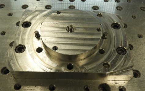
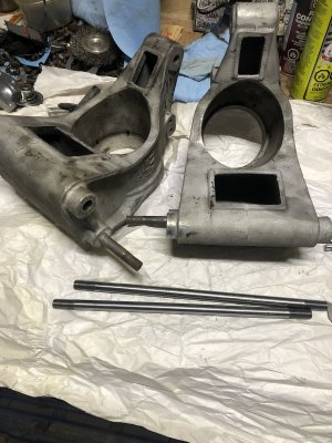
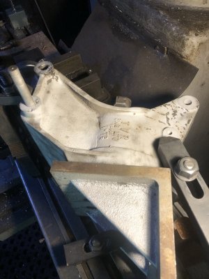
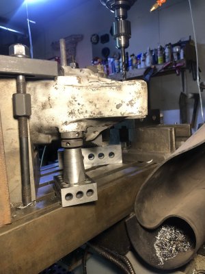
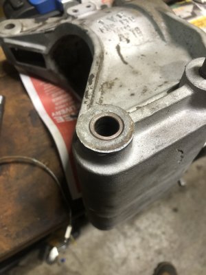
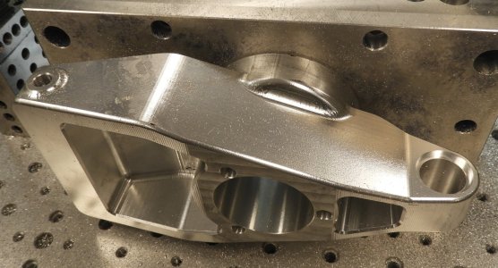
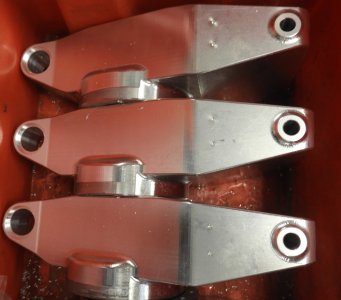
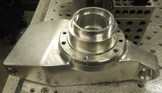
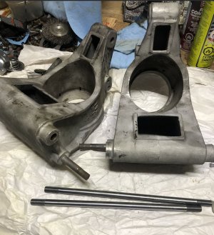
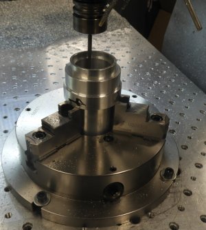
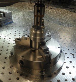
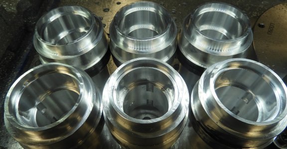
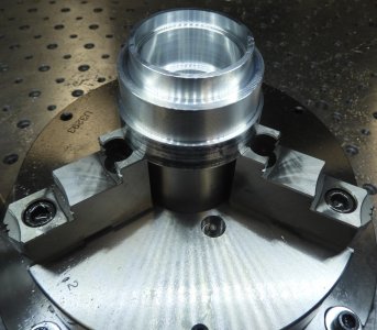
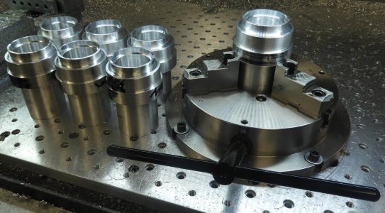
The fixture is very simple. I use the two dowels for alignment and location. The standing aluminum is only so the three 1/4-20 holes are only 0.05 away from the pocket in the housing (clear both top and sides). On the old fixture I was using the six 5/16-18 holes on the flange of the housing. The two problems were, having to remove the fixture each time to undo it, and also the fixture was 3 inches thick, limiting my cutter length. The Version 1 of this part was whole, with no sleeve. I changed the part because the alignment between front and back bores is critical on the part. As a whole, it was impossible to clock the opposite bore. Also impossible to check afterwards. I will still be using the original fixture for side and end operations.

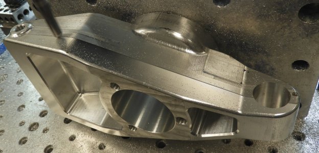
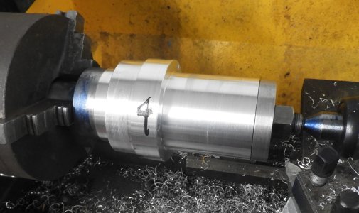
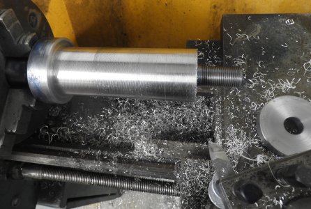
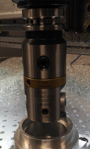
The final housing is being machined now. Next job will be to finish the sleeve bushings. This will be a surprise as you see the tooling I will be using to do it........
 

Attachments

  • DSCN1532.JPG
    DSCN1532.JPG
    433.7 KB · Views: 2

Matt-Aburg

Ultra Member
Here are some pictures from inside the Griffith shop. He has 3 cars in now with 2 more on the way.
 

Attachments

  • DSCN1552.JPG
    DSCN1552.JPG
    285.7 KB · Views: 6
  • DSCN1547.JPG
    DSCN1547.JPG
    441.2 KB · Views: 7
  • DSCN1548.JPG
    DSCN1548.JPG
    315.7 KB · Views: 6
  • DSCN1549.JPG
    DSCN1549.JPG
    472.2 KB · Views: 6
  • DSCN1550.JPG
    DSCN1550.JPG
    345.5 KB · Views: 5
  • DSCN1551.JPG
    DSCN1551.JPG
    396.9 KB · Views: 5
  • DSCN1553.JPG
    DSCN1553.JPG
    427.7 KB · Views: 5
  • DSCN1554.JPG
    DSCN1554.JPG
    295.2 KB · Views: 4
  • DSCN1555.JPG
    DSCN1555.JPG
    342.4 KB · Views: 4
  • DSCN1556.JPG
    DSCN1556.JPG
    466.6 KB · Views: 8

Stellrammer

Well-Known Member
Well the perfect storm has just hit. I am going to have to work triple time to close as much shop stuff as possible. I got the order for two of these housings. I will need a lathe for part of the work too, which is in-process. These parts are made out of 6061 Aluminum. I need to make 2 of each. For the critical bores in the bushings, I will be using the DINE fine boring head. I just ordered material and the boring head.

To begin with, here are screen shots of the parts. All yellow surfaces are critical, blue is clear, brown is tapped.
I recognize those, I’ve machined several sets from raw castings, a bit difficult to extrapolate tolerances from an ancient original one, with conventional measuring equipment.
 

Stellrammer

Well-Known Member
Here are some pictures from inside the Griffith shop. He has 3 cars in now with 2 more on the way.
I’ve been doing NLA parts for Lotus and TVR for quite some time now, a lot of idiosyncrasies from the early days of UK manufacturing to be avoided, or duplicated.
 

Attachments

  • 167B14F5-823F-4615-8313-B260B75E3B85.jpeg
    167B14F5-823F-4615-8313-B260B75E3B85.jpeg
    435.7 KB · Views: 7
  • 1B204FC7-6DF4-485B-A7E4-71A32BCEA86B.jpeg
    1B204FC7-6DF4-485B-A7E4-71A32BCEA86B.jpeg
    308.1 KB · Views: 7
  • 409E5023-ABBF-4E2E-AD34-6B17B602ADE5.jpeg
    409E5023-ABBF-4E2E-AD34-6B17B602ADE5.jpeg
    540 KB · Views: 7

Matt-Aburg

Ultra Member
I’ve been doing NLA parts for Lotus and TVR for quite some time now, a lot of idiosyncrasies from the early days of UK manufacturing to be avoided, or duplicated.
Looks like they went to a sleeve also on your last picture. They also don't use the same locking method for the shock bar. Still 1/2-20 by the looks of it on the ends of those bars.
 

Stellrammer

Well-Known Member
Looks like they went to a sleeve also on your last picture. They also don't use the same locking method for the shock bar. Still 1/2-20 by the looks of it on the ends of those bars.
Those are actually originals from the factory, one piece. They made a few different style uprights, this was from an later Griffith, maybe Vixen. These were only remove and replace the two rods , bore and bush them as well as the top bore. You can see they are much more substantial than the earlier S2 And Vixen ones.
The Griffin ones you are doing are quite early versions, they are poorly designed and thusly the changes you are making to them.
I’ve machined new ones from modified castings that have been altered to beef up those areas , mostly these go to the European market for the vintage racers.I was disappointed in the castings in that they were not heat treated, leaving them porous and gummy to work with.
The bearing surfaces were not difficult to do much to my relief, upon measuring everything including the bearings I found the bores were .003” under size, consistent with other original housings!
The next ones will be heat treated, I have fixturing to accommodate all the operations on my Excello , I can bore to Tenths even with the cheap a Narex copy boring head I have ,but it is not necessary to on these.
I had some originals scanned, and a well known custom machined one from one of the same castings I work with. The workmanship was alarmingly poor on all of them, rod holes out of alignment by 2 MM , angularity out of wack etc.
I found the factory put slots between the bearing bores for knock out purposes with a punch, I would hazard a guess that they didn’t use heat to fit the bearings. I’ve removed and replaced not only the shock rods but bearings with heat, the bearings fall out at less than 300 degrees. The .003” undersized bores respond well because of the expansion factor of Aluminum with out affecting the castings in any way.
Overall going to a billet is a very good solution, I just don’t have the ambition to go that way, nice to see you tackle it
 

Attachments

  • 40C5524A-5AEE-42B4-82E6-67F65AAEA37E.jpeg
    40C5524A-5AEE-42B4-82E6-67F65AAEA37E.jpeg
    430.5 KB · Views: 4
  • D230AFF4-3335-4547-BBA0-F8287C0861F9.jpeg
    D230AFF4-3335-4547-BBA0-F8287C0861F9.jpeg
    418.2 KB · Views: 4
  • F4397012-74DC-4A11-8ACD-042161A87AD4.jpeg
    F4397012-74DC-4A11-8ACD-042161A87AD4.jpeg
    361.7 KB · Views: 4

Matt-Aburg

Ultra Member
The .003” undersized bores respond well because of the expansion factor of Aluminum with out affecting the castings in any way.
Overall going to a billet is a very good solution, I just don’t have the ambition to go that way, nice to see you tackle it
The main bore for bearing in center on mine was about 0.003 undersized. I am making sleeves for that hole. The sleeve has bores both sides that take the race and a cylindrically ground shaft goes through. My customer wants them only 0.001 under. My last set was 0.0015-0.002 under. He wants them looser because they were "too tight." He does no use heat to shrink them as the design intention is. BUT, I think the solid 6061 is not as forgiving as a casting for press due to the porosity. I will be bringing first off (sleeve) over for test fit before I scrap the whole lot. I need the size signed off on in writing before continuing.

For the metal shaft that is STUCK in place by corrosion, surprisingly he did not want bushings there... Eventually the new bars will be frozen in permanently as the old ones are (on mine). On the other end of part there is a pivot point that has a design change on mine. We use plastic bushings and a steel bushing within... smart because plastic won't seize (from corrosion).

These cars do not see the road at all. They are show cars and get trailered from show to show. I think this might be another reason not to have a 0.003 pressfit ... ??? ....
 
Last edited:

Stellrammer

Well-Known Member
The main bore for bearing in center on mine was about 0.003 undersized. I am making sleeves for that hole. The sleeve has bores both sides that take the race and a cylindrically ground shaft goes through. My customer wants them only 0.001 under. My last set was 0.0015-0.002 under. He wants them looser because they were "too tight." He does no use heat to shrink them as the design intention is. BUT, I think the solid 6061 is not as forgiving as a casting for press due to the porosity. I will be bringing first off (sleeve) over for test fit before I scrap the whole lot. I need the size signed off on in writing before continuing.

For the metal shaft that is STUCK in place by corrosion, surprisingly he did not want bushings there... Eventually the new bars will be frozen in permanently as the old ones are (on mine). On the other end of part there is a pivot point that has a design change on mine. We use plastic bushings and a steel bushing within... smart because plastic won't seize (from corrosion).

These cars do not seethe road at all. They are show cars and get trailered from show to show. I think this might be another reason not to have a 0.003 pressfit ... ??? ....
My last modded parts went into a Vixen with a 2 liter Kent, turboed, 385 HP on Dino, the customer drove it home to the Midwest after , bold.
The other 3 Vixens locally that are in the same shop, the race only has 240 HP , naturally aspirated, hits 190kmph at Mosport. The 2 others are approaching that power but are now doing street duty.
The dude in the pic is the ex boss of the racing team at TVR, over from England, visiting Plunketts that evening.
Pic courtesy of Mark Brown, owner of that Vixen.
 

Attachments

  • FDA2CAA9-4CD4-4DF2-9F01-24A8AEFB3BD3.jpeg
    FDA2CAA9-4CD4-4DF2-9F01-24A8AEFB3BD3.jpeg
    536.7 KB · Views: 5

Matt-Aburg

Ultra Member
The project has moved to near the final stages. I have the housing bodies finished except for miscellaneous holes that get done on the drill press. I had my friend with a industrial VMC do the 6 inch reamed hole and 1.163 diameter bores. In the first picture, I am removing the mismatch. Second shows it finished ..(no sanding required). 3rd is a group of them. 4th is finishing the sleeve bushing on a spigot. 5th is the spigot. Last picture is one sleeve inserted into the housing.

Today I have to set my router with new tooling and surprise fixture (for the next entry). This is to do the bores accurately, rigidly and to size and surface finish within +.0000 -.0005.
 

Attachments

  • 1.JPG
    1.JPG
    366.8 KB · Views: 6
  • 2.JPG
    2.JPG
    417.5 KB · Views: 4
  • 3.JPG
    3.JPG
    352.5 KB · Views: 4
  • 4.JPG
    4.JPG
    315.4 KB · Views: 5
  • 5.JPG
    5.JPG
    481.9 KB · Views: 5
  • 6.JPG
    6.JPG
    379.9 KB · Views: 6
Last edited:

Matt-Aburg

Ultra Member
I’ve been doing NLA parts for Lotus and TVR for quite some time now, a lot of idiosyncrasies from the early days of UK manufacturing to be avoided, or duplicated.
Just wondering if these are the ones you mentioned?
 

Attachments

  • TVR.JPG
    TVR.JPG
    251.9 KB · Views: 4

Matt-Aburg

Ultra Member
Time to DINE !!

I am now at the end stages of the sleeves. This will hopefully go smooth as silk. My customer wants the sleeves to be only 0.001 press. I am VERY leary of this due to @Stellrammer saying his are @ 0.003 shrink. I also measured 0.003 shrink on the originals along with my brother in law, the master toolmaker. Version 1 ended up at 0.002 press, which my customer says is too tight. He does not shrink them. I am going to make 1 at his request on my NFG part, for testing... (yup, I made 2 extra in case and needed them). I will be bringing it over finished at the 2.249 size and a drawing to which he will have to sign off before I scrap all the parts... !!! >>> ... !!!

I think with only 0.001 shrink, he will need to use green Loctite.. Also, could it be that because the part is made from 6061 billet instead of a porous casting, that the press fit would be different?

Anyway... without further delay, here is the new boring head and holding fixture. This could be a bit scary boring a 2K and a feed-rate of about 20 IPM. I will make sure not to bottom out by 0.005
 

Attachments

  • DSCN1611.JPG
    DSCN1611.JPG
    408 KB · Views: 8
  • DSCN1613.JPG
    DSCN1613.JPG
    635.9 KB · Views: 8
  • DSCN1614.JPG
    DSCN1614.JPG
    272.7 KB · Views: 8
Last edited:

Stellrammer

Well-Known Member
Just wondering if these are the ones you mentioned?
These pictured are from an early Vixen, dual shocks, not he same as what you are making.
The ones you are making and the ones I do from castings are the modified version of the standard ones. The standard ones are reproduced and very inexpensive, but have the same failings as the originals, which is why people are paying 3 times as much for ones that hold up.
 

Matt-Aburg

Ultra Member
These pictured are from an early Vixen, dual shocks, not he same as what you are making.
The ones you are making and the ones I do from castings are the modified version of the standard ones. The standard ones are reproduced and very inexpensive, but have the same failings as the originals, which is why people are paying 3 times as much for ones that hold up.
I was at the Griffith shop today with sample bore sizes. We ended up at 2.248. I am alos going to add a slight lead ing maunually for the first 3/8 to 1/2 so that they are stared straight. I will be doing all the inserts tomorrow, and seting the green glue and locktited SHCS. The glue will set, then I will be pushing zerk hole, overflow hole and 2 spring pins for added insurance. I also need to make the shock bars and misc. bushing out of 3/4 CRS. Delivery finally on Monday next week.

We talked about the UK guy that sells all the castings you mentioned, and also many other parts including the shafts he needs. Looks like he will need to get them from there this time. The UK Castings are over 900 pounds, which is like 1500 CDN. I may bump the price next time by 300 more and be about 2K. Better product for slightly more $$$ than the copied poor design for England.
 

Matt-Aburg

Ultra Member
All done DINEX boring. I held the 2.248 within 0.0002 and the top bore is 2.499 within 0.0002. Surface finish is very good. I spin 2000 RPM and feed at 10 IPM. Do one spring pass and they are good to go.

Tomorrow I have fitting and green Loctite and thread locker red (both are 500 degree to break seal). After it sets, I need to put in Zerk fitting, and 1/8 excess grease escape hole, and two 3/16 split pins (also red 500 degree). I have miscellaneous bushings and the shock bars to make....

Delivery for Monday of this set !!
 

Attachments

  • DSCN1624.JPG
    DSCN1624.JPG
    318.4 KB · Views: 8
  • DSCN1626.JPG
    DSCN1626.JPG
    450.3 KB · Views: 8
  • DSCN1629.JPG
    DSCN1629.JPG
    373.6 KB · Views: 8
Top