• Scam Alert. Members are reminded to NOT send money to buy anything. Don't buy things remote and have it shipped - go get it yourself, pay in person, and take your equipment with you. Scammers have burned people on this forum. Urgency, secrecy, excuses, selling for friend, newish members, FUD, are RED FLAGS. A video conference call is not adequate assurance. Face to face interactions are required. Please report suspicions to the forum admins. Stay Safe - anyone can get scammed.
  • The 2026 Calgary Area Meetup is set for Saturday May 30th at 10am. The signup thread is here! Robinhood has graciously offered to host the meetup again this year. Please note that you MUST RSVP to the notice linked above if you wish to come.

Other Basic Electronics, Multimeters, & Oscilloscopes

This thread is about basic electrical, electronics, Multimeters, and Oscilloscopes. It is an outcome of interest that various members have expressed about these subjects.

@Janger , @Johnwa , and @kevin.decelles have all recently obtained a starter Oscilloscope so I think the timing is good for a thread like this.

The primary resource will be a book (available on Amazon in paper or kindle) called Electronics for Dummies by Kathleen Shamieh. The book isn't a requirement, but it always helps to have a reference of some kind to facilitate discussion. Other references might get added as the thread progresses.

I'm not picturing this thread as a course, just a good place to ask questions, find answers, and share knowledge and experience about basic electrical knowledge and testing.

As always, a good time and lots of great jokes are expected!
 
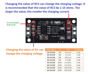
This little module would do the job although some rewiring would be required.
https://www.aliexpress.com/item/1005008606216476.html At about $11 with shipping.

This would have to be powered from the output of the 5V regulator rather than the 9V.

1780676676066.png

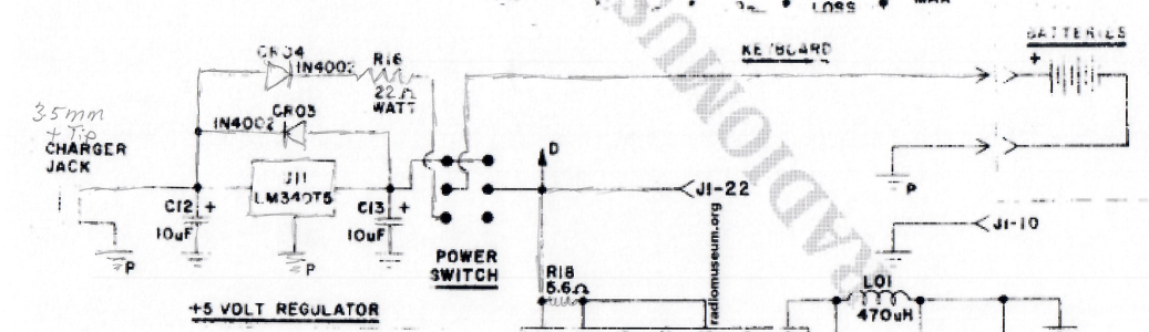
Thickening the lines on the drawing shows that the NiCad batteries are only charged from 190mA to 150mA when the voltage reaches 1.41V per cell and the unit is switched off. Long term charging would likely not be good them.

When it's switched on the power for the unit comes from either the fully charged 4.8V battery or the 5V regulator. If powered and switched on from the AC Adaptor the 5V just trickle charges or holds the unit fully charged.

To use the NiMH charger module the 22 Ohm resistor would be removed and the switch rewired to supply 5V into the charger module from where the 22 ohm resistor connects to the switch.

It's not known at this point if the charger module will discharge the battery when the unit is switched off and the AC adaptor is not plugged in. A blocking diode would fix that like the CR34 does but then the closed loop charging in the module will likely not work because it can't sense the battery voltage.

1780677047460.png

So there's the basic electronics of this little charging module.
 
To use the NiMH charger module the 22 Ohm resistor would be removed and the switch rewired to supply 5V into the charger module from where the 22 ohm resistor connects to the switch.

It's not known at this point if the charger module will discharge the battery when the unit is switched off and the AC adaptor is not plugged in. A blocking diode would fix that like the CR34 does but then the closed loop charging in the module will likely not work because it can't sense the battery voltage.

I'm no expert & this might be more geared to RC chargers that have a slightly different mission: evaluate the likley depleted & mixed voltage state of a pack, initially trickle them in a safe & evaluative manner, then (safely) charge them at relatively high-C (vs home use chargers) because you are usually perpetually swapping fresh packs at the field & charging is rather boring compare dto flying. NICD are more rugged & resilient to charging (overcharging) so the circuits & algorithms between the 2 chemistries are typically different. My friend bought a very similar looking AliExpress board but it was dedicated to NIMH (not NICD) for a similar application to yours. Essentially replacing a maintenance wall wart adapter that failed, so basically utilizing the existing jack because it was problematic to open the case & insert fresh batteries. I bet its a similar charging brain as my 110VAC universal charger which works perfectly on NIMH size & count of cells. So far I am super happy with it. I even put a known dud cell in it & it detected it, refusing to charge.
1780679169562.png

Unrelated but cautionary tale. I bought a 'reputable' 12v 18A-hr LifePO4 battery for field work to replace my heavy deep cycle, but needed dedicated charger for that chemistry. Attaching my post-mortem review.
1780679329039.png
1780679425923.png

Ended up getting this one which serves dual duty as maintenance float charger for regular batteries, so far so good.
1780679535214.png
 
Takes 4 screws that have lock washers to get inside. And then it's a bit of a tricky wicket to actually open it. Not meant to have the NiCads pulled and replaced with fresh set.

Trying to decide if it's worth buying the batteries and then selling it or selling it as is with the indication that it needs batteries to be portable but works without them.
 
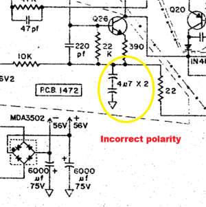
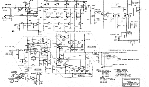
As discussed earlier in this thread - professional electrical schematics with errors.

Can't stress enough the importance of taking pictures of items before disassembling for replacement or repair. This time it was a vintage guitar power amplifier where I was upgrading old components that included replacing all the electrolytic capacitors. All but one of these capacitors were polarized. I had the original electrical schematic that was tucked inside the unit. My method for replacing was the following:

- identify which cap I was replacing (a little tricky because unlike some circuit boards there were few if any identifying marks on the board or schematic such as "C1, C2, C3..." or polarity indicators on the circuit board itself).
- take a picture of the original installed cap on the circuit board to make sure that I had the correct polarity recorded.
- remove that old cap and immediately install the new cap.
- double check correct polarity of newly installed cap referencing the picture and the schematic.
- move on to the next.

That was going great until I was about to replace two series capacitors and realized the schematic showed the polarity opposite of the way they were actually installed. I couldn't assume anything because I never seen the amplifier powered "ON". I tried to follow the logic of the circuit. Not an electronics guru like some of you guys but I was able to determine from the schematic the physical capcitors were installed correctly but the schematic was showing the wrong polarity. I think it was safe to assume that the original caps were correct because they were same vintage as the others and the unit had a long history (if you believed the seller's story which I heard second hand from the buyer). But I never try to assume anything no matter how obvious it may appear.

This is where if I had got off track or distracted and never took pictures I might have second guessed myself. Then I would have used the schematic to determine the proper polarity installation. I always planned on using my Dim Bulb Tester just in case but still something would have shown to be problematic. In the end, I believe taking pictures and going through each replacement slowly saved me from a serious headache.

Traynor TS-200 schematic error.png Series Caps 2.jpg

There was a thought to mark the circuit board itself with a "+" to record polarity. Next time.
 
As discussed earlier in this thread - professional electrical schematics with errors.

Can't stress enough the importance of taking pictures of items before disassembling for replacement or repair. This time it was a vintage guitar power amplifier where I was upgrading old components that included replacing all the electrolytic capacitors. All but one of these capacitors were polarized. I had the original electrical schematic that was tucked inside the unit. My method for replacing was the following:

- identify which cap I was replacing (a little tricky because unlike some circuit boards there were few if any identifying marks on the board or schematic such as "C1, C2, C3..." or polarity indicators on the circuit board itself).
- take a picture of the original installed cap on the circuit board to make sure that I had the correct polarity recorded.
- remove that old cap and immediately install the new cap.
- double check correct polarity of newly installed cap referencing the picture and the schematic.
- move on to the next.

That was going great until I was about to replace two series capacitors and realized the schematic showed the polarity opposite of the way they were actually installed. I couldn't assume anything because I never seen the amplifier powered "ON". I tried to follow the logic of the circuit. Not an electronics guru like some of you guys but I was able to determine from the schematic the physical capcitors were installed correctly but the schematic was showing the wrong polarity. I think it was safe to assume that the original caps were correct because they were same vintage as the others and the unit had a long history (if you believed the seller's story which I heard second hand from the buyer). But I never try to assume anything no matter how obvious it may appear.

This is where if I had got off track or distracted and never took pictures I might have second guessed myself. Then I would have used the schematic to determine the proper polarity installation. I always planned on using my Dim Bulb Tester just in case but still something would have shown to be problematic. In the end, I believe taking pictures and going through each replacement slowly saved me from a serious headache.

View attachment 85516 View attachment 85517

There was a thought to mark the circuit board itself with a "+" to record polarity. Next time.
Before you close it up I'd measure the voltage across the two caps. It the end closes to ground is more negative than the side connected to the 22K and 390 Ohm I'd say the schematic is correct.
 
Before you close it up I'd measure the voltage across the two caps. It the end closes to ground is more negative than the side connected to the 22K and 390 Ohm I'd say the schematic is correct.

The positive connection from the last capacitor to ground is on the opposite side of a 22 ohm resistor that is connected to the -56V rail. Can't be seen in that portion of the schematic. Therefore, I reasoned that portion of the circuit is more negative than ground which means the schematic is wrong. Does that seem to make sense?

Online PDF of Schematic

When powered "ON" in series with the Dim Bulb Tester I checked the voltages on the "-" and "+" power rails. As I increased the wattage of the bulbs (if it stays bright something isn't right) I kept an eye on those voltages and the current draw. Finally, when it appeared all was good but still with circuit protection in place I applied full voltage for at least 10 minutes. Voltages and current stabilized fairly quick and remained constant as components warmed up.
 
@jcdammeyer
@combustable herbage

Link posted in post #247.
I hope the schematic is wrong because apparently somebody used it in a school that taught music for many years. Those caps are definitely vintage and no signs of anybody replacing anything recently. So how could the caps be wrongly installed for 50 years without anyone noticing? Again, all assumption on my part but fairly good evidence to suggest that I could be correct.
 
Ok, what I should have done just to confirm this 100% is measure the voltage across the capacitors, black lead to ground and red to the node. Negative voltage result and the schematic is wrong. Positive voltage result and the schematic is correct.

I did that test just now with the Dim Bulb Tester in place (150W bulb in series to add some protection with minimum voltage drop). Result = -48V. Schematic is incorrect regarding polarity of capacitors.
 
Hi Guys,

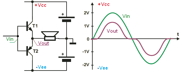
Its quite common to wire two capacitors in series but back to back where a non polarised capacitor is required. The actual capacitor value is halved but the voltage rating stays the same. Often done because a non polarised capacitor is not available and takes account of the AC voltage that appears at that point in the circuit. Often you will find this done where an output to a loudspeaker is fed from a transistor push pull pair. Very rare in valve/tube circuits.
 
@jcdammeyer
@combustable herbage

I appreciate the input. Never hurts to take a second look. The last test I just did should have been the first test.

You can add me to the list of those who think the schematic is just wrong.

Well done Sir!

Beyond the polarity issue, what the hell does 4u7 even mean? I've never seen that before. Anyone? To me, it just reeks of a shoddy schematic. I see other issues in the schematic too.

While I admire your usage of the brightness of a test light, the end result could have also been catastrophic. In high impedance circuits, it won't work and might even disrupt or damage the circuit.

You do realize that you are the perfect candidate for a good DMM or even a small oscilloscope....... We can help with that you know........ Not just with the purchase, but also the usage. My personal opinion is that you would learn really fast. Never too old to learn!
 
You can add me to the list of those who think the schematic is just wrong.

Well done Sir!

Beyond the polarity issue, what the hell does 4u7 even mean? I've never seen that before. Anyone? To me, it just reeks of a shoddy schematic. I see other issues in the schematic too.
Its 4.7 micro farad often times they use the greek symbol mu and so they just use the small letter u.

The Greek letter μ (mu) has several uses depending on the context:

  1. As a prefix for units of measurement. For example, the symbol μ is used to represent the micro prefix which is equal to 10−6 in SI units.
 
While I admire your usage of the brightness of a test light, the end result could have also been catastrophic. In high impedance circuits, it won't work and might even disrupt or damage the circuit.
Based on my research a Dim Bulb Tester is standard test equipment for audio repair people. It's use and designs are documented all over the internet and in audio repair books. It's only purpose is to give a heads up that something in the circuit is seriously wrong. Based on my understanding using it to power audio equipment like an old tube radio or this vintage guitar amp when their condition is unknown or after repair is how you can help prevent catastrophic damage. Like with any tool it has a specific use. Might not be good or safe for testing just any electronic device.
 
Its 4.7 micro farad often times they use the greek symbol mu and so they just use the small letter u.

The Greek letter μ (mu) has several uses depending on the context:

  1. As a prefix for units of measurement. For example, the symbol μ is used to represent the micro prefix which is equal to 10−6 in SI units.

I never had an issue with the u. I am aware of that meaning. It gets used a lot for that because the symbol for micro is not readily available on most keyboards. In fact, I used it myself because there is no micro symbol on my phone that I know of. I expect it is there but I don't know where.

My issue was with the use of 7 vs an F or f. I've never seen that.
 
I never had an issue with the u. I am aware of that meaning. It gets used a lot for that because the symbol for micro is not readily available on most keyboards. In fact, I used it myself because there is no micro symbol on my phone that I know of. I expect it is there but I don't know where.

My issue was with the use of 7 vs an F or f. I've never seen that.
Often on schematics values use the letters too. For example.
4.7 Ohms is the same as 4R7 and you don't have to write Ohms.
So guess these values:
4R7
4K7
47K

We see it less with capacitors but it's really just an approach:
4.7uFd or 4.7uF is the same as 4u7
 
We see it less with capacitors but it's really just an approach:
4.7uFd or 4.7uF is the same as 4u7

In all my life, I've never seen that and I've been involved in Electronics for 50 years.

That said, 4.7 is much more common than 4. But I confess that I don't know the real reason why. I used to think it had more to do with overlapping ranges for a given tolerance than any real functional reason. But that only partly makes sense. The theory goes to hell in a hand basket when the tolerances tighten up.
 
Back
Top