Maybe someone mentioned already but some guys set the compound at high angle & increment the DOC that way. Dimensionally this works but if your material and/or tooling doesn't like this 'creep up on it thou by thou' mode, then its of less value. Another option: I have my coated/steel inserts set up on different tool holders than my uncoated 'sharper' inserts for aluminum, so its easy to just plop on a that cutter with say 10 thou to go & do the finishing operation with that if it makes sense.
-
Scam Alert. Members are reminded to NOT send money to buy anything. Don't buy things remote and have it shipped - go get it yourself, pay in person, and take your equipment with you. Scammers have burned people on this forum. Urgency, secrecy, excuses, selling for friend, newish members, FUD, are RED FLAGS. A video conference call is not adequate assurance. Face to face interactions are required. Please report suspicions to the forum admins. Stay Safe - anyone can get scammed.
-
Several Regions have held meetups already, but others are being planned or are evaluating the interest. The Calgary Area Meetup is set for Saturday July 12th at 10am. The signup thread is here! Arbutus has also explored interest in a Fraser Valley meetup but it seems members either missed his thread or had other plans. Let him know if you are interested in a meetup later in the year by posting here! Slowpoke is trying to pull together an Ottawa area meetup later this summer. No date has been selected yet, so let him know if you are interested here! We are not aware of any other meetups being planned this year. If you are interested in doing something in your area, let everyone know and make it happen! Meetups are a great way to make new machining friends and get hands on help in your area. Don’t be shy, sign up and come, or plan your own meetup!
You are using an out of date browser. It may not display this or other websites correctly.
You should upgrade or use an alternative browser.
You should upgrade or use an alternative browser.
4140 crankshaft modifications - propeller hub build
- Thread starter phaxtris
- Start date
I only power feed in one direction, back off the tool, spin out reset & repeat.
I have no doubt that this is an issue - especially with Carbide Inserts. They simply don't cut the same in both directions. Perhaps not the triangular inserts set on equal angles, or round inserts, but the rest do for sure. And I wouldn't trust triangular or round either unless the dimension doesn't matter.
I have been known to cut in both directions but NEVER on finish passes. I ALWAYS back off and rewind manually, then set the depth of my next cut based on what happened on the previous cut. Otherwise you have no idea what you will get. Especially with inserts on different angles, but also with HSS.
Maybe someone mentioned already but some guys set the compound at high angle & increment the DOC that way.
Yes, it was mentioned. But I think it's only of value if you are trying to creep up on a dimension instead of using the results of the previous cut. And quite frankly, I don't think creeping up on a dimension is as reliable as an experience based cut using the prior cut.
Hitting a precise dimension is not as simple as trusting the dials or even a DRO. Too many variables and too many factors. Experience based cuts are much much more reliable.
Creeping up on a dimension can work too, but it is also subject to many variables that are all conspiring to ruin your project. I only do that with honed sharp HSS that I trust in the material I'm cutting. Time might convince me to trust inserts for Aluminium or Stainless, but that time is still a ways off into the future.
In summary, for me there are really only two ways to hit a precise dimension cutting on a lathe. Experience based cuts with Carbide or HSS, and fine cuts with very sharp HSS.
Grinding is also an option, but we are discussing cutting here.
Last edited:
Thanks to @RobinHood I have some more 4340!
It sure is soggy, Rudy and I put it in the drawer.....I surely couldn't get it out on my own ! Had to hook up a chain fall to get it out !
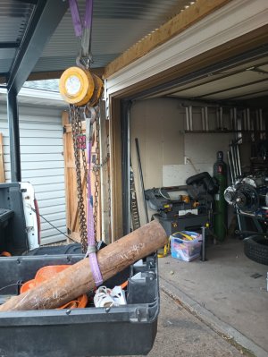
It sure is soggy, Rudy and I put it in the drawer.....I surely couldn't get it out on my own ! Had to hook up a chain fall to get it out !

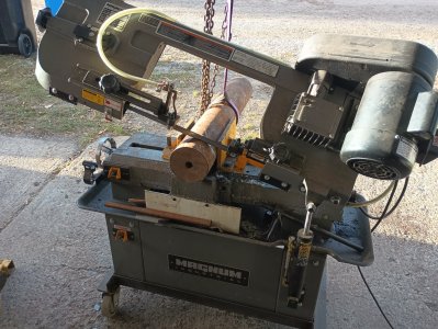
152lbs, thing weighs more than I do
Anyhow, made a little bit of progress, took 25 min to cut a piece off with the 7x12 and whatever blade I have in there, and 1.5 hours of rough turning to get here
One thing, I cannot get the chips to break this time, tried all sorts of doc"s with different feed speeds, no luck on that front, just massive bird nests, I'll keep at it tomorrow if I have time, maybe I'll find a combination that works
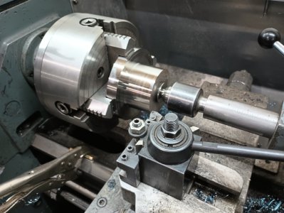


One thing, I cannot get the chips to break this time, tried all sorts of doc"s with different feed speeds, no luck on that front, just massive bird nests, I'll keep at it tomorrow if I have time, maybe I'll find a combination that works
Looks like you are using a WNMG insert. It's my experience and opinion that WNMG TRIGON inserts usually break chips better than other insert styles except maybe square which is similar. However, it's important to use one designed for your material if you want good chip breaking. I think a big nose radius is also a factor because of the tendency to curl the chips a bit more. All that said, some materials just like to make bird nests. When I really need chip breaking on such a material, I grind my own HSS and I grind in a very aggressive chip breaker.
I wonder if you could make an aggressive chip breaker that might be held on by the insert clamp. Maybe even make a whole new clamp to do that in the clamp itself?
RobinHood
Ultra Member
I turned some 4140 yesterday. 4340 should behave similarly.
TNMG (I think it’s a 432), 570 to 770 rpm, 0.050” DoC, 0.008 to 0.010 “/rev. The lathe has to work a bit, but nothing that’s going to hurt or break anything.
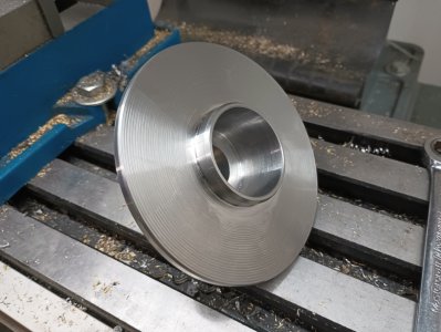
The large OD is 3.5”, the snout is 1.25”.
(Yes, the boss of my part is already scratched up because the fit was a bit too tight…)


TNMG (I think it’s a 432), 570 to 770 rpm, 0.050” DoC, 0.008 to 0.010 “/rev. The lathe has to work a bit, but nothing that’s going to hurt or break anything.
The large OD is 3.5”, the snout is 1.25”.
(Yes, the boss of my part is already scratched up because the fit was a bit too tight…)
I'm using the same insert from the other piece, tried new corners, it was breaking on that
I'm 560rpm, tried anything from .020-.040 doc, I'll check the chart, I think I was more like .oo48/rev, I'll check the chart again, i dont think i have the power for a .050 @ .010 cut
I have a few other inserts to try as well, I'll have to take a look at the machine tonight
I'm 560rpm, tried anything from .020-.040 doc, I'll check the chart, I think I was more like .oo48/rev, I'll check the chart again, i dont think i have the power for a .050 @ .010 cut
I have a few other inserts to try as well, I'll have to take a look at the machine tonight
I must have been running it much harder the first time around
Breaking chips now with .05 doc and .083 per rev at 560rpm, it does pretty well at that chip load. I don't think I will push it any harder, there is a pretty rough section of the rack I dont want to make any worse...one of these days I should take it off and braze/file that section, I don't imagine I can get a new one
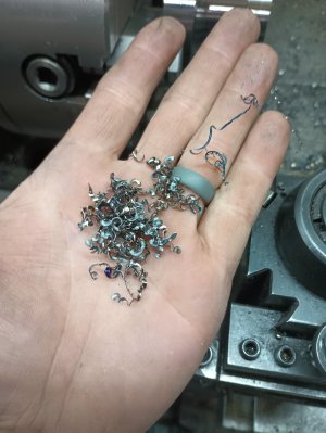
Breaking chips now with .05 doc and .083 per rev at 560rpm, it does pretty well at that chip load. I don't think I will push it any harder, there is a pretty rough section of the rack I dont want to make any worse...one of these days I should take it off and braze/file that section, I don't imagine I can get a new one


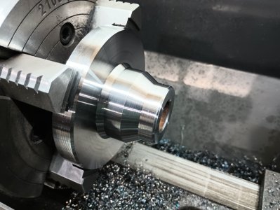
Success! i had to force myself to go out there, but i managed the bore to .002-.0025 undersize, my heart was pounding
The out feeding must have been the problem as was mentioned/discussed, i had no issues hitting the dimension this time
now its a matter of turning the face, counter bore, and drilling the 6 holes, but at least the critical +/- .0005 dimension is complete, time to take my win and go on to other sunday chores
Yay!
This video shows a shop made cross slide lock that does not involve drilling into the dovetail sidewall for a retention screw like most Asian lathes. His mod is an eccentric cam friction lock that is actually kind of nice & tidy. The videos are 2 parts, build & demo. This is demo.
Go to abut 11:00 mark where he shows a clear demonstration of table drift as tool starts cutting as evidenced by DRO, with & without lock employed. A non-locking cross slide is the root of many evils.
Thanks for that @PeterT. And especially for the time marker.
Nice accessory.
I'm just a bit confused about what the cam bears against. Is it the top half or bottom half of the cross-slide? I assume the top. And the screws attach to the bottom half (the saddle).
In other words, this gadget attaches on the opposite side of the cross-slide Gibb and pushes the cross-slide body against the matching saddle dovetail. But the photos suggests otherwise?
Anyways, this is a nice lock.
I'm not sure if he specifically said at some point, but I suspect he is using the threaded holes in the saddle where the travelling steady typically mounts for his gadget mounting bracket. Or in my case, where the DRO encoder plate is mounted :/ Then the brass eccentric pulls the table down & locks it that way. So it may or may not be perfect in that position for other lathes depending on layout & steady usage preferences. But my point was more about how things slip & slide on the cutting surface even though the dial registers the same number.

So it may or may not be perfect in that position for other lathes depending on layout & steady usage preferences.
I guess it never occurred to me that he might be using those holes. It's a good idea. Although, new holes further toward the operator might reduce the need for a long actuator.
Since I want to put my dro scale inside my cross-slide, it would not affect me like it would you. When I take my cross-slide off, I'll prolly drill and tap some new holes for this or so be other usage. I don't really like the idea of adding anything to the working area.
But my point was more about how things slip & slide on the cutting surface even though the dial registers the same number.
Yes, point taken. I've always known that effect was there - especially with heavy cuts, but it's great to see that particular aspect quantified on someone's lathe.
But ponder this...... That's only the cross-slide component of the effect. It ignores flexing in the compound, toolpost, tool holder and tool! This is one reason why I don't use the triangle inserts. I can't help but be concerned about the high forces they generate at right angles to the lathe spindle axis.
I always thought it would be neat to mount an array of strain gauges to the tool shank & other downstream surfaces at different surfaces/orientations & see the data real time through various cutting procedures or tooling. selections The gages & amplifiers are spit cheap but the acquisition box / display software is spendy. I've seen people hook up strain gages to Arduino for numerical display force equivalent but it would be more interesting to see the wave forms superimposed onto one another. Or, we learn hand scraping LOL
I always thought it would be neat to mount an array of strain gauges to the tool shank & other downstream surfaces at different surfaces/orientations & see the data real time through various cutting procedures or tooling. selections The gages & amplifiers are spit cheap but the acquisition box / display software is spendy. I've seen people hook up strain gages to Arduino for numerical display force equivalent but it would be more interesting to see the wave forms superimposed onto one another. Or, we learn hand scraping LOL
Today was a royal PIA. Hip XRays at the Hospital, walk 6 miles uphill in the cold wind to get a covid needle, then another 6 miles to get blood drawn to test for lyme disease, then finally home with SWMBO. Promptly headed for the shop for some r&r.
Yup, that thing uses the follow rest mounting holes. My factory lock is a grub screw pushing the gib. Very solid. Same end result.
I'd love to use strain gauges too. Might be way better than eyeballing everything and doing SWAGs. Both are prolly way better than his DRO.
Dan Dubeau
Ultra Member
Looks great!Little bit of progress, counter bore done, faced
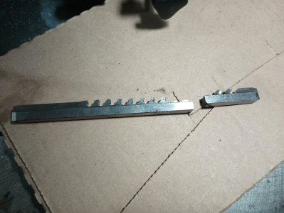
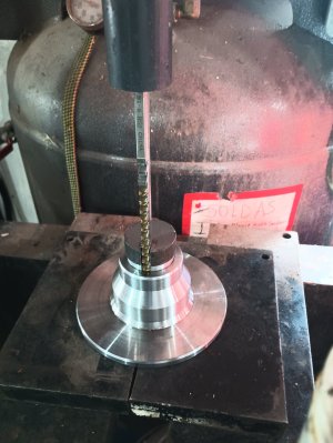
Next up, holes and the keyway
View attachment 53542

