• Spring 2024 meetup in Calgary - date Saturday, April 20/2024. discussion Please RSVP Here to confirm and get your invitation and the location details. RSVP NOW so organizers can plan to get sufficient food etc. It's Tomorrow Saturday! you can still RSVP until I stop checking my phone tomorrow More info and agenda
  • We are having email/registration problems again. Diagnosis is underway. New users sorry if you are having trouble getting registered. We are exploring different options to get registered. Contact the forum via another member or on facebook if you're stuck. Update -> we think it is fixed. Let us know if not.
  • Spring meet up in Ontario, April 6/2024. NEW LOCATION See Post #31 Discussion AND THE NEW LOCATION

YYC: Slat for deck of CNC machine

Wes D.

Member
Hello,
First off, I have no idea what I'm doing :rolleyes:

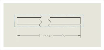
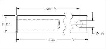
I need some parts made. I've made an attempt at CADing up what I need and have tried to produce a drawing, which should be attached to this post.
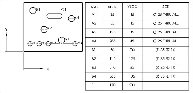
Just in case my drawing isn't clear: There are 6 counterbored holes to accept low profile M10 socket screws. Then there is an array of 3 by 13 holes that are threaded to accept M12-1.75 on 5cm centers.
I am going to need 7 of these. What I'm asking for is two fold:

- A quote on what someone here would want to make these for me. I'm flexible in that I can pick up and provide the steel (just want it out of vanilla hot rolled weldable..) or just pay for a finished product. The downside to this approach is that I double many hobbiests have a machine that have a 95cm long work envelope.

- Advice on how to make the drawing more standard. If I'm going to shop out for quotes on this part, I'd like to have the drawing have as little confusion as possible.

Thanks,
-W
 

Attachments

  • RouterSlat.pdf
    188.9 KB · Views: 74

Dabbler

ersatz engineer
What sort of timeframe are you looking for? Are you in Calgary or is shipping required? Is this a home project or for a commercial use? What are the tolerances that are required for your intended use?

P.S. 95 cm is no problem for this part, even on my old mill.
 

Wes D.

Member
What sort of timeframe are you looking for? Are you in Calgary or is shipping required? Is this a home project or for a commercial use? What are the tolerances that are required for your intended use

My timeframe is not overly tight, I'd like to have them by the end of October if possible. I can be flexible on this, I do have some projects I'd like to tackle before Xmas and these slats will help out a lot.

I live in Calgary.

Home project.

For tolerances, this is where my ignorance will show. I honestly don't know. This is a hobby machine; I'm not making aircraft parts on it. If what I get isn't tight enough, I'd probably just fasten a fixture plate to it and machine that to be flat to the machine for whatever project I'm doing. If anything I'd like to be under on the 150mm width, and the most important thing is that they are close to each other in height. If they are all nearly the same height and 1mm thicker than the drawing, I won't care. This is the sort of stuff I have no idea how to capture in a CAD drawing.
 

Jwest7788

Joshua West
Administrator
My timeframe is not overly tight, I'd like to have them by the end of October if possible. I can be flexible on this, I do have some projects I'd like to tackle before Xmas and these slats will help out a lot.

I live in Calgary.

Home project.

For tolerances, this is where my ignorance will show. I honestly don't know. This is a hobby machine; I'm not making aircraft parts on it. If what I get isn't tight enough, I'd probably just fasten a fixture plate to it and machine that to be flat to the machine for whatever project I'm doing. If anything I'd like to be under on the 150mm width, and the most important thing is that they are close to each other in height. If they are all nearly the same height and 1mm thicker than the drawing, I won't care. This is the sort of stuff I have no idea how to capture in a CAD drawing.

In machining, tolerance is often on the scale of +/- 0.001" (0.0254mm), sometimes even half of othat, or down to 0.0001" in tight tolerance applications.

+/- 1mm won't be an issue as all for many members here.

JW
 

Wes D.

Member
This is where I always get lost on talking about tolerance. When I say I want something to be 1 inch long, and I measure it and it is 1.001, I get the tolerance. But how do you specify tolerance on flatness? keeping under 0.0001" of lift or skew across 3 feet is no easy task...

...not that I'd even be able to measure it, if it wasn't.

As I mentioned, it is more important that the parts are similar in height, than if they adhere to the dimensions of the drawing. Is this something that can be encompassed in a drawing? Or is it only through conversations like this that these things get sorted out?
 

Alexander

Ultra Member
Administrator
If you want to apply tolerances to your drawing you should use GD&T (geometric dimensioning and tolerance) GD&T is a bunch of symbols and rules to remember. They tell the person manufacturing your parts what the allowable deviation from nominal is. Before i go applying tolerances to your drawing i must say in the province of AB we more commonly use imperial measurement. All material available here will be in imperial so i will suggest changing the thickness from 12.5mm to .5" Here are some simple rules that apply to your drawing. First add decimal points even to the round numbers. Then in the ledger leave a note such as .x = +/- .75mm .xx= +/-.125mm this will help the machinist understand what is required. .75mm is a assumed for fabrication if no tolerance is given and .125mm is the default tolerance for machined parts IMO.
 

Alexander

Ultra Member
Administrator
GD&T Symbol Control Type Name Summary Description
GDT_Symbols_Straightness.jpg
Straightness Controls the straightness of a feature in relation to its own perfect form
GDT_Symbols_Flatness.jpg
Flatness Controls the flatness of a surface in relation to its own perfect form


Sigmetrix_GDandT_Symbol_Parallelism.jpg
Orientation Parallelism Controls orientation of a feature which is nominally parallel to the primary datum of its datum reference frame
Sigmetrix_GDT_Symbol_Position.jpg
Location Position Controls the location and orientation of a feature in relation to its datum reference frame
Sigmetrix_GDT_Symbols_Circularity.jpg
Circularity Controls the form of a revolved surface in relation to its own perfect form by independent cross sections
Sigmetrix_GDT_Symbols_Cylindricity.jpg
Cylindricity Like circularity, but applies simultaneously to entire surface
 

Wes D.

Member
Wow, thanks @Alexander
Just knowing 'GD&T' so I can google it is a huge help and now I've got some wikipedia pages to digest. I do have what should be quick questions:

- You mention adding notes to the ledger. I come from a scientific background and I think my definition of ledger is something different that those in the engineering / fabrication space. Are we talking about the 'notes' in the bottom? Or something different?

- The 39 threaded holes in the part, I'd like to take metric fasteners. You mentioned to change my dimensions to imperial. Is it common to have a mix of the two? Or should I just leave everything in metric because there is one feature that I can't reasonably translate to imperial. Although specifying a 0.472441-14.5142852498 tpi thread may be funny to me, I'm assuming the person reading the drawing won't think it so.
 

Jwest7788

Joshua West
Administrator
I can't imagine why you wouldn't be able to mix measuring systems. (Mm VS inch)

As long as each and every dimension marks which unit it's in, there should not be room for mistakes. Though, it probably isn't common? @Alexander ?


Sent from my iPhone using Tapatalk
 

Wes D.

Member
I guess another thing I've wondered: how do I show that the array of holes through the middle are all threaded? Is what I've done sufficient? Or do you put a callout on each hole? Is there someway to show that 'all of these are just like this one'
 

Alexander

Ultra Member
Administrator
The qestion about labeling the holes is easy. Label one hole 12mm-1.75 x39 the person reading the drawing will know there is 39 threaded holes on this part.
 

Alexander

Ultra Member
Administrator
Personally I would prefer to see all dimensions in one unit of measurement. But it is extremely common to have meteric threads on an imperial drawing. Hey if you want to do your drawing in meteric that's good too. The price will likely go down if you make the overall dimensions in a nominal inch size. That way they don't need to machine the stock to size.
 

PeterT

Ultra Member
Premium Member
Wes.D what CAD software did you use? Aside from useful comments made thus far, I can add a few more.

- Long skinny parts like yours can be challenging to fit on typical 'paper' document size. What can be beneficial is a capability called 'broken section'. This only works well when your part has longish sections of essentially the same stuff. ie no important detail or information lost by omitting it. For example the tube portion of a long driveshaft where you don't have to necessarily see all the in-between shaft, just the ends & total length. It can also be used if there is a consistent, repeating pattern like your matrix of holes. But probably best to have some auxiliary full view visual just in case. Basically you want to convey more than enough information to ensure there is no head scratching or ambiguity. The guy making the part would much prefer a few more pages of drawings to look from different vantages vs. something minimal that has him guessing. Guessing will cost you money :)

- depending on your software, it might be able to automatically spit out a hole table with a button click. This eliminates a whole bunch of drawing dimensions & sections. I'm not familiar with Fusion 360 but its a low cost 3D package others on the forum are using. Assuming it can mimic what other industrial programs can do, the result hole table may look like attached. This conveys useful info to a manual machine operator. Essentially saying: from this datum go over X-amount & Y-amount & make this hole type. Now if you are providing a '3d part' as a digital file to a CNC manufacturer, you don't even really need the 2D 'paper' drawing although its still very useful & often requested anyway. But in that case, you email the 3d file to vendors in specific format, they slurp that into their software & can quote directly.

Not sure if this above or below your current abilities but giving you the broad view.
 

Attachments

  • SNAG-9-14-2017 0002.jpg
    SNAG-9-14-2017 0002.jpg
    9.5 KB · Views: 54
  • SNAG-9-14-2017 0001.jpg
    SNAG-9-14-2017 0001.jpg
    9.8 KB · Views: 52
  • SNAG-9-14-2017 0000.jpg
    SNAG-9-14-2017 0000.jpg
    42.9 KB · Views: 48

Wes D.

Member
Now if you are providing a '3d part' as a digital file to a CNC manufacturer, you don't even really need the 2D 'paper' drawing although its still very useful & often requested anyway. But in that case, you email the 3d file to vendors in specific format, they slurp that into their software & can quote directly.

Interesting. I guess I shouldn't be surprised, but I never thought that I would be able to just send a 3d file to a manufacturer. What format do they usually want?

I am using Fusion 360. It is what I used to CAD up the slat, and is also the tool used to generate the drawing. It _may_ have the ability to generate a hole table, I'll take a look. Although, I'd have to admit, with no real CAD training and just learning via the internet, I'm probably not even at what one would call 'proficient'. I'm pretty open to help, so if there are any members that use Fusion and they want to help out, I'm more than willing to share the project with them.

Work has ramped up significantly, so I was going to let this sit here for another week, before attempting to incorporate all the feedback and add it to the drawing before sending it out. My hope is to be fishing for quotes by the end of next week.

Thanks for your input.
-W
 

Wes D.

Member
Thanks for the feedback.
Now that works has rolled its latest tide, I can get back to this. I have attempted to incorporate feedback where I could.

@Alexander - I have added the decimals and tolerances. Basically what you assume is the default is what I went with. I also changed the thickness to be a default imperial measurement. I have also labelled the threaded hole as a multiple to show it is to be applied to all its friends. Thanks for you feedback.

@PeterT - I tried to incorporate a 'broken section' but after...well...let's just call it cussing, a couple beers and a lot of frustrated internet searching, I gave up. I also tried to put in a hole table, but currently fusion only supports a parts list/table. It is on their roadmap, and has been for 2 years. Not holding my breath.

Attached is the newest iteration. Seeing that I didn't warrant a nibble from the forums, can anyone recommend a local shop that can take this on and deliver at a reasonable price? If not, I'll likely just send it to the first half dozen shops that Google gives me.

Thanks,
-W
 

Attachments

  • Router Deck Slat Drawing v4.pdf
    195 KB · Views: 66

RobinHood

Ultra Member
Premium Member
Hi Wes,

Question: is your dimension of 150mm wide critical? Reason for the question: hot rolled flat bar comes in 1/2" thick by 6" wide by 10' or 20' long. 150mm works out to about 5.90". It would save you $s if no cutting/machining were required on the long side of your parts.

Hot rolled has scale on it. So, again, how critical is your 7mm countersink depth? Are you just looking for the low profile M10 SHCS to lie flush or slightly below the surface?

Next: you specify 50.0mm spacing longitudinally for your holes. Problem could be, with that many holes in a row (13 in your case), that the last hole no longer lines up with whatever it bolts to because the errors in spacing are cumulative and, in the worst case, if all are on the high side, the last hole could be out by ~ 3/4 of a hole diameter. I would reccommend you reference each of the 13 hole triplets from a common reference point; ie: the left hand edge of your part. That way you greatly reduce alingment issues.

I have a milling machine that could handle the 950mm length.

Send me a pm and we can talk if you want.

Cheers, Rudy
 

Wes D.

Member
The width, unfortunately is probably the most critical measurement I've got on that drawing. When we talk about $s of saving in not having to machine those edges, what order of magnitude are we talking? I have to assume that drilling and tapping all those holes is going to be an order of magnitude more cost than machining 14 edges.

The M10 low profile doesn't need to be flush, and it would be better to be too low, than too high.

The hole spacing thing is doable. Although it would add 13 stacked lines to the top of that part of the drawing. I'll get that done when I'm next sitting at my laptop. I'm pretty sure you grok what I'm aim for: Holes on 5cm centers.

....and PM sent.
 

PeterT

Ultra Member
Premium Member
Maybe this dwg will help you guys. I needed to refresh my brain on this stuff anyway with new software version. Agree 100% with RobinHood plus a few more things to noodle.

- re the M10 c/sunk mount holes, according to my selection drop down, regular M10 socket head cap screw c/sink depth = 0.394" (10mm nominal I guess). That's leaving very little (0.106") bottom meat for your 0.5" plate if you want the cap screw head fully recessed. And if the c/sink tool has a pilot head that could be an issue too. You might want to check machinery handbook, but this was my quickee conclusion.
- if above is M10 shoulder screw, c/sink reduces to 0.276" (7mm nominal). But you would have to source these specific fasteners & they may not be as common as you think.
- if you want to use regular cap screws but its ok to have the heads protrude, then we can doctor the prescribed c/sink depth, say 0.100" or 0.150" ..something nice :)
- easier yet from machining standpoint, no c/sink at all. So ask yourself why this is required. If you need it great, but if you can get by with just a hole & a washer, saves a lot of setup. The head & hole is all clearance so its not registering to anything in terms of the fastener.

- dwg example dimensions result if I define the upper left hand corner as datum & all hole dimensions originate from there
- I used inch dimensions on a metric part (just to prove I can). But if someone has metric/inch switchable DRO then you should go all inch or all metric
- your 150mm width works out to 5.906" as mentioned, so conceivably could be made from 6" nominal stock leaving 0.094" cleanup material. Personally, you have the plate on the mill for a lot of work, why not clean the edges & simultaneously make everything parallel & square including the edges unless the machine itself is a limitation. Your machinist may specify minimum rough stock in this case.
- btw your 940mm length works out to 37.008". I know you are rounding off to 37" for simplicity but just an FYI. When I labelled the hole dimensions I just defined x.xxx (thou) for consistency
- ignore my material, it must have been part of dwg template
- caveat: I'm a self-taught amateur to there may well be BS in what I'm saying above ^^

- HRS will be a cruddy finish so investigate what fly cut finish looks like. I know.. more machining & more $$ & slightly thinner piece.
 

Attachments

  • router plate 3.PDF
    93.7 KB · Views: 59

PeterT

Ultra Member
Premium Member
Oops, just noticed a boo-boo on my part. You have an array of 13 sets of holes in X direction, I only had 12. New PDF.

Another idea - have you considered having the entire part cut & pilot hole spotted by a 2D water jet or laser company? Depending on accuracy & what you are set up to do, your job could be as simple as drilling out the pilot holes to finish tap hole size & hand tapping (in case of threaded) & similar operation for the cap screw holes. This wont do anything for surface finish so you will have to figure that part out beforehand. I sent a small job to Clearcut for water jetting & was happy with the price & their willingness to work. Laser Equation does laser, but they may guide you about localized hardening of the holes (= potential tapping issue). If you drop by for a visit they can show you samples to visualize what the edges & kerf etc. looks like. Nothing beats machined surfaces of course, but that's a tedious number of holes = more operator time on manual machine. This stuff is more what 2D cnc action can do more readily over a manual machine at least.
 

Attachments

  • router plate 4.PDF
    95.8 KB · Views: 57
Last edited:
Top