• Scam Alert. Members are reminded to NOT send money to buy anything. Don't buy things remote and have it shipped - go get it yourself, pay in person, and take your equipment with you. Scammers have burned people on this forum. Urgency, secrecy, excuses, selling for friend, newish members, FUD, are RED FLAGS. A video conference call is not adequate assurance. Face to face interactions are required. Please report suspicions to the forum admins. Stay Safe - anyone can get scammed.
  • The 2026 Calgary Area Meetup is set for Saturday May 30th at 10am. The signup thread is here! Robinhood has graciously offered to host the meetup again this year. Please note that you MUST RSVP to the notice linked above if you wish to come.

Working on my South Bend 9C

Hi Michael, Guys,

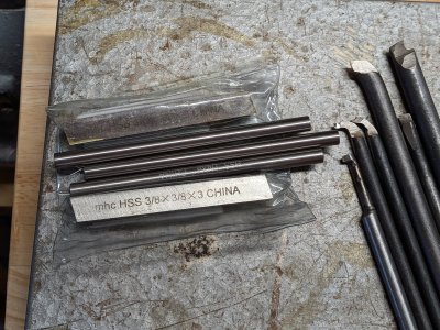
Almost all my HSS tool steel has come from salvage, scrapyards, engineering firms scrap boxes etc. I don't think that I've actually ever bought any. It might pay you to make polite enquiries to local firms, here in the UK engineering companies are more and more using carbide interchangeable tooling and throwing out unwanted/unneeded HSS tools.
 
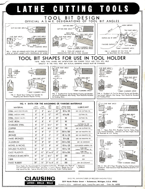
This is very interesting for getting a grip on angles for grinding. The back rake angles are what caught my eye. Also I appreciate that the chart includes some plastics, hard rubber, and micarta (and I had mostly been planning to use aluminum as a reference point).
 

Attachments

  • Clausing cutting tools.png
    Clausing cutting tools.png
    2.4 MB · Views: 18
This is very interesting for getting a grip on angles for grinding.
This chart does not include threading. For you, the most important thing to remember is that the side clearance angle on the nose needs to be slightly greater than your thread helix angle which varies by pitch and increases significantly for multi start threads. Someone earlier said to start with a regular thread and perfect that first. I agree with that, but don't forget to increase your side angle accordingly when you transition to multistart.
 
I think the chart drawings shows the angles for bits held in a tool holder being held in a lantern tool post, if this is the case, may need to adjust angles to be held in a quick change tool holder as the tool bit is generally held parallel to the cross feed. The tool bit held in a tool holder and then in a lantern tool post can mean the shank of the tool bit can be at very different angles.
It looks like figure #1 and figure #3 are the only ones that take this into account, and the column that gives the “true back rack”needs to be followed, not just going by the drawings.
I
 
Hi Bandit, Yes I agree, the pictures are a bit deceptive. A true representation should clearly show the angles from a reference surface. Nobody uses a rocker tool post now a days .
 
If anyone has a similar reference for more modern tool holding that would be great. I haven't come across one yet but I'm probably just looking in the wrong places.
 
If anyone has a similar reference for more modern tool holding that would be great. I haven't come across one yet but I'm probably just looking in the wrong places.
Micheal,
Max needed a custom cutter for a left hand thread with four degree sides. Although he does it on a tool and cutter grinder I think you'll find the video of value as he explains the geometry. He also makes a couple of mistakes (which he corrects) but for me it seems to keep me focused and catching them confirms that I am grasping the concept.

 
Nobody uses a rocker tool post now a days .

Hey hey hey.... Quite a few of us have really old lathes that we prefer to use rockers on. I'm one of them. I have a 1880s vintage lathe that I prefer to use a rocker on.
 
Well, I hope that was a bit tongue in cheek. One lathe has a lantern post, a 4sided block and a small quick change, the other larger lathe has the 4 sided block and a change post.
Sometimes there is a bit of swearing and other language cause I don’t have a lantern post for it and have to do some thinking how to get into an area to machine. Yes, one day it to may have lantern post.
And note, me old shaper uses a lantern post without a rocker!
 
Hi Bandit, Yes I agree, the pictures are a bit deceptive. A true representation should clearly show the angles from a reference surface. Nobody uses a rocker tool post now a days .
Ok Guys, I give up ! I'm staggered to hear that people still use them. I thought that they were old hat...
 
This is very interesting for getting a grip on angles for grinding.
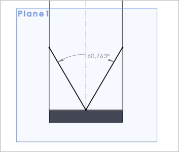
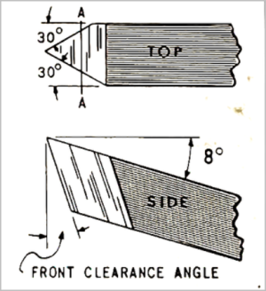
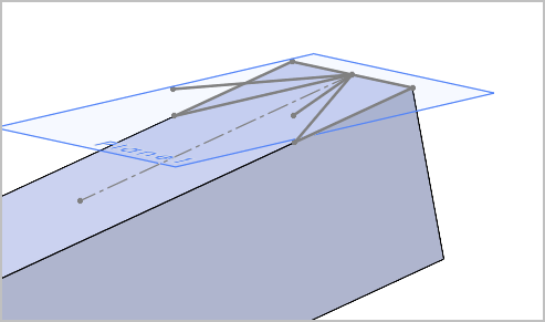
This is typically how its presented in older texts because the blanks were ground, either using an angle jig or up against a birdsmouth template to achieve the thread angle. The top of the tool is the reference plane, so to get desired back rake angle, the whole tool is angled to point upward in the toolpost. Most know this, but maybe worth repeating: this most always does not apply to replaceable threading inserts. On inserts the rake is integrated into the insert itself even though the tool shank / pocket is horizontal. Now we get into the weeds where many common inserts are for general pupose threading & have other compromises. Some systems use shims under the insert to tweak the angle for different alloys which accomplishes adjustments just like the HSS chart.

IMO this isn't quite as serious as many make it out to be, at least on hobby machining in most common materials. In fact consider the same issue back to HSS blank example. If you grind a blank exactly 60.0 deg relative to the HSS blank top plane, that works out to ~61-deg when tool points up at 10-deg rake angle & therefore is what the resultant thread included angle will be. Enough to worry about? probably not unless you are doing more radical materials / rake angles, but just know its there. Often you will see people set the grinder rest to some angle & grind the 60-deg on that reference plane, but this is more about achieving back rake on the facets, it does not fix the included angle issue. Technically you would have to set the angle fence to the correct angle or kind of visually project the birdsmouth gage at rake angle.


1782061851639.png1782062436175.png1782062472158.png
 
Last edited:
Ok Guys, I give up ! I'm staggered to hear that people still use them. I thought that they were old hat...
We do a lot of stuff which is laughable in industry. Grinding cutters? never. Single point fly cutters? No use a 5 insert or more indexable cutter. Manual machining? no. But for one off parts manual is much faster than any CNC setup and most of us are not making multiple parts. Maybe ELS type combined solutions are quicker than manual. @kevin.decelles ? @gerritv ? @jcdammeyer ?

Edit -> I do find “wizards” or similar functions useful on CNC machines. This avoids drafting/modelling in fusion, then doing the CAM, then loading and proving the program on the machine. Like the face milling wizard. fill in the form with the dimensions, depth of cut, step overs/step downs, tool & tool speed, etc. and it spits out the gcode all on the cnc machine. I understand more expensive and better equipment can be much better on with the machine tool interfaces. Hurco maybe, Mazak? Or much worse as well e.g. anything Fadal? @Alexander told me once Heidenhain was very good in this regard.
 
Last edited:
Hey, a lantern tool post maybe old hat, but I also have a few old hats. Sometimes people use the lantern post because that’s what they learned on, that’s what the lathe came with, etc. In some cases a person doesn’t see or feel that something else is needed, maybe not willing to make on or put the price out.
I have no idea what a quick change of med quality or better would could cost for a big old lathe that turning 16 inch’s plus.
Like I said, my bigger lathe is set up to run the 4 sided block or the quick change post, it mostly has the block on it. I will admit that I don’t have that many tool holders for the quick change, which might be some of the issue. It also seems a lot of my turning is kind of one off stuff, and often requires some odd bit grind or shape, maybe never used again without a regrind. Also I don’t have much in carbide tool bits, that may slowly change.
 
Seems like everything I'm turning up is at least referencing the same set of angles as that Clausing material. Wouldn't be surprised if many are drawing from that or similar from back in the day. Not finding much on plastics, but if the numbers for other materials are the same across reference sources, then the Clausing numbers still seem like a good starting point.


Engineer's black books has the same numbers as well! Just lists "thermoplastics", but that's as good a starting point as any.
 
But for one off parts manual is much faster than any CNC setup and most of us are not making multiple parts. Maybe ELS type combined solutions are quicker than manual. @kevin.decelles ? @gerritv ? @jcdammeyer ?
Yes and no. As long as there aren't fancy curves etc. then I agree manual is faster. Especially when you consider the time to draw the part, create the G-Code, set up the machine zero's for that G-Code, have the proper tools and lengths set.
Edit -> I do find “wizards” or similar functions useful on CNC machines. This avoids drafting/modelling in fusion, then doing the CAM, then loading and proving the program on the machine. Like the face milling wizard. fill in the form with the dimensions, depth of cut, step overs/step downs, tool & tool speed, etc. and it spits out the gcode all on the cnc machine. I understand more expensive and better equipment can be much better on with the machine tool interfaces. Hurco maybe, Mazak? Or much worse as well e.g. anything Fadal? @Alexander told me once Heidenhain was very good in this regard.
However I also agree with 'wizards' etc. In fact although my ELS started out as a digital logic version of a German electronic gearing costs of encoders quickly put that to rest and I changed to a processor.

And then the consensus of opinion was that it should also include X axis (cross slide) motion for full automatic threading. Now truth be told I rarely thread on the lathe but the ELS is in use all the time.
1. Face off the part and set the Z zero.
2. Key in or find and save the END point (negative value from 0) for turning to diameter.
3. Now I have power feed with BEGIN/END settings for turning multiple passes to reduce the diameter or enlarge the bore.

That's what's missing on the mill unless you move the metal blocks that trip the limit switches for the power feed. (Which I rarely did).

And yet in effect that's one of the things we want. An easy way to face a part. To cut a slot to depth with multiple passes. Obviously an arc would be wonderful.

All with almost wizards but not quite. And I think that tool is still missing for milling machines. So instead I write G-Code on the fly to do it.
 
Last edited:
Seems like everything I'm turning up is at least referencing the same set of angles as that Clausing material. Wouldn't be surprised if many are drawing from that or similar from back in the day. Not finding much on plastics, but if the numbers for other materials are the same across reference sources, then the Clausing numbers still seem like a good starting point.


Engineer's black books has the same numbers as well! Just lists "thermoplastics", but that's as good a starting point as any.
Hi Michael, These pictures make more sense to me !
I do just use a preset guide with the angles for certain jobs. I have a reference groove in the grinding table and the guide slides into it.
I think that I posted pictures of them recently.
 
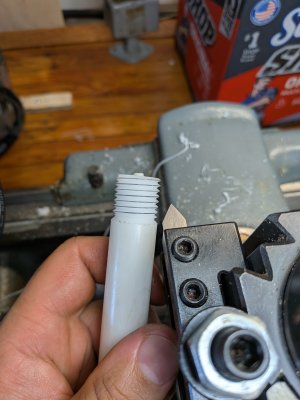
@Susquatch a first attempt at single point threading (with a self-ground tool).

Is it good? Probably not.

Do I have anything to verify it against? No, it's 12tpi on some random diameter of delrin.

BUT I did it and I now at least understand the basic process. I promised I would get to it in time! (You can call me Molasses Michael)

Now, so many questions about what I need to do next 😛
 

Attachments

  • PXL_20260624_214107252.jpg
    PXL_20260624_214107252.jpg
    1.4 MB · Views: 11
Back
Top