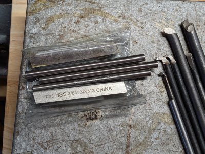
I know you are not.
But I am old and I do what old people do. Nag, nag, nag.


I know you are not.
But I am old and I do what old people do. Nag, nag, nag.


This is very interesting for getting a grip on angles for grinding.
Micheal,If anyone has a similar reference for more modern tool holding that would be great. I haven't come across one yet but I'm probably just looking in the wrong places.
Nobody uses a rocker tool post now a days .
Ok Guys, I give up ! I'm staggered to hear that people still use them. I thought that they were old hat...Hi Bandit, Yes I agree, the pictures are a bit deceptive. A true representation should clearly show the angles from a reference surface. Nobody uses a rocker tool post now a days .
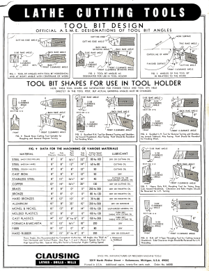
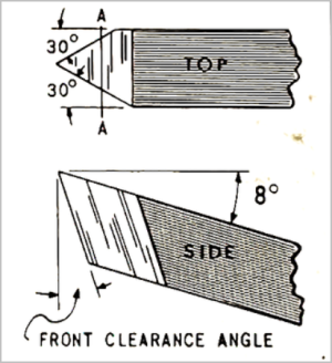
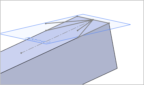
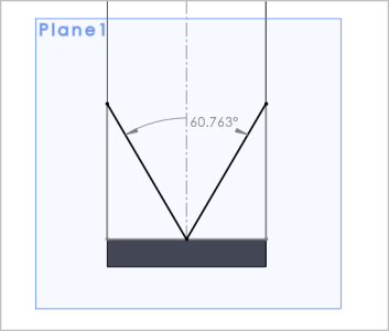
This is typically how its presented in older texts because the blanks were ground, either using an angle jig or up against a birdsmouth template to achieve the thread angle. The top of the tool is the reference plane, so to get desired back rake angle, the whole tool is angled to point upward in the toolpost. Most know this, but maybe worth repeating: this most always does not apply to replaceable threading inserts. On inserts the rake is integrated into the insert itself even though the tool shank / pocket is horizontal. Now we get into the weeds where many common inserts are for general pupose threading & have other compromises. Some systems use shims under the insert to tweak the angle for different alloys which accomplishes adjustments just like the HSS chart.This is very interesting for getting a grip on angles for grinding.
We do a lot of stuff which is laughable in industry. Grinding cutters? never. Single point fly cutters? No use a 5 insert or more indexable cutter. Manual machining? no. But for one off parts manual is much faster than any CNC setup and most of us are not making multiple parts. Maybe ELS type combined solutions are quicker than manual. @kevin.decelles ? @gerritv ? @jcdammeyer ?Ok Guys, I give up ! I'm staggered to hear that people still use them. I thought that they were old hat...

 littlemachineshop.com

Yes and no. As long as there aren't fancy curves etc. then I agree manual is faster. Especially when you consider the time to draw the part, create the G-Code, set up the machine zero's for that G-Code, have the proper tools and lengths set.But for one off parts manual is much faster than any CNC setup and most of us are not making multiple parts. Maybe ELS type combined solutions are quicker than manual. @kevin.decelles ? @gerritv ? @jcdammeyer ?
However I also agree with 'wizards' etc. In fact although my ELS started out as a digital logic version of a German electronic gearing costs of encoders quickly put that to rest and I changed to a processor.Edit -> I do find “wizards” or similar functions useful on CNC machines. This avoids drafting/modelling in fusion, then doing the CAM, then loading and proving the program on the machine. Like the face milling wizard. fill in the form with the dimensions, depth of cut, step overs/step downs, tool & tool speed, etc. and it spits out the gcode all on the cnc machine. I understand more expensive and better equipment can be much better on with the machine tool interfaces. Hurco maybe, Mazak? Or much worse as well e.g. anything Fadal? @Alexander told me once Heidenhain was very good in this regard.
Hi Michael, These pictures make more sense to me !Seems like everything I'm turning up is at least referencing the same set of angles as that Clausing material. Wouldn't be surprised if many are drawing from that or similar from back in the day. Not finding much on plastics, but if the numbers for other materials are the same across reference sources, then the Clausing numbers still seem like a good starting point.
Rake and Relief Angles for high-speed steel lathe tool bits.
These rake and relief angles are for high-speed steel lathe tool bits. Material Side Relief Front Relief Side Rake Back Rake Aluminum 12 8 15 35 Brass 10 8 5 to -4 0 Bronze 10 8 5 to -4 0 Cast iron 10 8 12 5 Copper 12 10 20 16 Machine Steel 10 to 12 8 12 to 18 8 to 15 Tool Steel 10 8 12 8...
Engineer's black books has the same numbers as well! Just lists "thermoplastics", but that's as good a starting point as any.