• Scam Alert. Members are reminded to NOT send money to buy anything. Don't buy things remote and have it shipped - go get it yourself, pay in person, and take your equipment with you. Scammers have burned people on this forum. Urgency, secrecy, excuses, selling for friend, newish members, FUD, are RED FLAGS. A video conference call is not adequate assurance. Face to face interactions are required. Please report suspicions to the forum admins. Stay Safe - anyone can get scammed.

Working on my South Bend 9C

We may be approaching "too many cooks in the kitchen" but I have some thoughts.

You could inspect the reamer / MT3 Alignment bar to see if it's bent by setting it up between centers on the lathe. A made in place center on the chuck end (guaranteed to be concentric with the spindle) and a dead center on the tailstock end would be the most precise. You could even turn the dead center yourself and put it in a drill chuck, if there's misalignment between the centers, it doesn't really matter to the runout measurement.

If you confirm the reamer is bent, https://www.mcmaster.com/3016N16/ might be a decent option. Kinda pricey at $90USD+ shipping but it should be reliable. Otherwise your local metal supplier should carry some TGP (turned, ground, polished) shaft. Shorter, larger diameter is more likely to not be bent.
 
You could inspect the reamer / MT3 Alignment bar to see if it's bent by setting it up between centers on the lathe. A made in place center on the chuck end (guaranteed to be concentric with the spindle) and a dead center on the tailstock end would be the most precise.
According to the links I saw they are centerless ground. That means initially turned between centers, heat treated, then centerless ground. That means origonal center drills are no longer related to the OD concentricity. There is a different sort of grinder (forgot the name) which traverses accross the work on centers, but I'm pretty sure not the process on these bars.
 
No way it's this straightforward... Couple thou of brass shims that should rotate the headstock in the right direction. Pic and 2 videos 180° apart again.

Are you saying you did this shimming & as a result it dialed the bar in parallel to the ways? Or you are wondering out loud if it could be this easy?

Assuming the bed is un-twisted (we dont know that yet, but just pretend for now) and the HS happens to be rotated (yawed) in the horizontal plane as when looking down on the lathe, that will point the test bar off-parallel to the ways which is what your dial is saying. You could do the math but all it takes is a tiny amount to make a relatively large displacement at the end of the test bar. Back to your shim picture, it is rotating the HS in the horizontal plane (good), but because the shim is sitting on the dovetail its also shimming the spindle in an upward amount, which we likely dont want. So when you ar emeasuring the test bar in/out dviation, you should also measure any up/down movement.

Stepping back a bit, was there any reason to assume the HS was removed in its life, or a different HS swapped on?
 
Are you saying you did this shimming & as a result it dialed the bar in parallel to the ways?
This. I got a wild hair and adding some shim stock at that one corner out of curiosity.

So when you ar emeasuring the test bar in/out dviation, you should also measure any up/down movement.
Hmmmm, I will see if I can rig something up. I'm not sure I can get that dial indicator in position - would a DTI give useful information here?

different HS swapped on?
Oh yeah, this is NOT the original HS. The original was the pre-A/B/C version with a trashed spindle and no way to get a replacement. In some ways I am surprised it was as close as it was.
 
Headstock is a separate piece from the bed. "Alignment" is keyed to the far side v-way, and the headstock is clamped under the ways fore and aft.

I'm gunna start by suggesting that you try to fix the worst of the worst first knowing it won't be perfect.

Assumptions:

1. You can borrow a precision level and maybe get someone to help you un twist your bed.

2. The stand is what it is. You are gunna use it as is and take the good and bad however it finds you. A new stand is a future improvement.

3. That spindle bar you bought is reasonably concentric. Even if it isn't perfect, it can be used.

Begin by measuring and marking the concentricity of the test bar as is. Just find the runout and mark all the high spots say every 2" from the spindle nose out and write the high runout at the high spots wherever they are. Then leave the bar installed.

Untwist the bed using a precision level and Shims at the bed bolts.

Use the closest and furthest high spots on the bar to align the spindle using your choice of shim material. Try just moving it before shimming it. Front to back pointing is more important than up and down pointing. So fix front to back first and then up/down. Might have to interpolate to find the best average.

Align the tailstock as best you can using whatever method you prefer.

That should look after the worst problems so call it quits at this point.

 
Not taking anything away from ensuring the lathe bed twist is minimized, but lets do some simple math to show the relative impact of a cocked headstock vs other alignment variables.

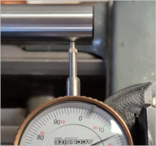
Your 2 videos showed the indicator traversing down the test bar. Both showed about the same max deviation at the end of the bar with 180-deg rotation between them. So for now lets just assume the bar is linear, not bent, because it would be harder to explain how a bent bar could exhibit this result. Lets use 0.015" deviation for round number example. PS - what I noticed as you traversed down the bar was the needle was going jiggley as you cranked but it didnt seem to be ~ 1/2 deflection at 1/2 bar length (like ~ 0.007" at 6" mark on a 12" long bar). Most of the deflection seemed to occur the end 1/3 or so. Maybe paralax or something else going on, but set that aside for now.
1794614977923.png

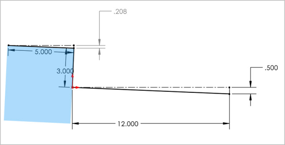
Here I have sketched a 'cad calculator' layout looking down on the lathe. The blue block simplistically represents your headstock footprint over the ways (actual HS dimensions TBC). The black lines to right represent the angled test bar extending from the spindle perpendicular to HS block as a result of being angled. I conciously made the drawing crazy exaggerated just so the deviations & amounts would ve visible. If I input 0.500" as the deflection observed at end of test bar, it says I require 0.208" shim on the HS corner to satisfy the geometry. So its a simple trig ratio: 0.208/0.500 = 0.416 so Shim = 0.416 * Measurement If we plug in 0.015" actual deviation, we get 0.006" shim. I'm not sure how 0.006" compares to how much wiggle room your HS can free play between the ways or size of shim you actually used. But the point I'm trying to make is how sensitive the relationship is all other things being equal. You would have to twist the bed a significant amount to observe this same deflection amount if the HS was perfectly aligned to the ways. I have a different CAD calculator for that, but lets just start here. If you have more accurate values for HS dimensions & bar length, let me know & I can adjust accordingly. I suspect the HS block position & shim points are probably not accurate in this simple sketch, but it was just to demonstrate a point.

1794615694417.png
 
what I noticed as you traversed down the bar was the needle was going jiggley as you cranked
Yeah as soon as I engaged the hand crank it went all higgledy jiggledy. If I were to pause it settles. If I could engage the feed without rotating the spindle that would be interesting.

I can try to get some numbers later.

Also of note is plenty of bed wear sooooo.
 
Back
Top