• Scam Alert. Members are reminded to NOT send money to buy anything. Don't buy things remote and have it shipped - go get it yourself, pay in person, and take your equipment with you. Scammers have burned people on this forum. Urgency, secrecy, excuses, selling for friend, newish members, FUD, are RED FLAGS. A video conference call is not adequate assurance. Face to face interactions are required. Please report suspicions to the forum admins. Stay Safe - anyone can get scammed.

Working on my South Bend 9C

So, @Golem Pens I appreciate your efforts to make the readings make sense for us. But I think the end result is confusing us. Let's keep it simple.

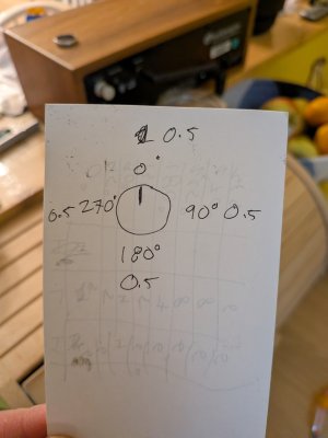
Please create a chart that has 17 rows and three columns. The rows start at zero and increment by 45 degrees going around 360 degrees TWICE to make sure it repeats.

The three columns are spindle angle, at the collet, and at 3.5"

Don't try to simplify the readout. Just give us the actual reading on the DTI.

Obviously, you need to make sure that the DTI remains within its range of authority throughout the tests. You can zero it if you want before you start, but it might be better to preset it to 10 thou.

You can do all 16 measurement up close first and then switch to doing all at 3.5" out on the reamer. Don't rezero or re-index the DTI between face measurements and end measurements. The important thing is to index all the angle points so they are all taken at the same position and then only rotate the spindle in the one direction so that any hysterysis in the indicator is always biased the same way.

Both rotations should get the same results at each index point. If they don't, then we have a bigger problem to figure out.

Again, the purpose for doing these tests is to see if the reamer is concentric (out of round) and if the axis of the reamer is concentric with the axis of the spindle. See my earlier post for a better description.

Your earlier test tells us that the axis of the spindle is not being bent out of position by cutting forces. So I scratched that off the list.
 
@Susquatch

Got it, will do. A few clarifying questions:

1) You no longer want a deflection test, correct?
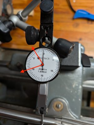
2) For my specific DTI, how would you want this exemplar reading recorded? With the red arrows indicating the two extremes of the dial sweep.
- 10.1 to 5.4?
- 13 ticks?
- Other?
 

Attachments

  • 1000010068.jpg
    1000010068.jpg
    2.5 MB · Views: 2
Not sure about the actual reamer but if it was a typical offshore model I'd be shocked if it wasnt slight banana. Even if the blank was turned between centers, fluted etc. it was subsequently heat treated before grinding the flutes. Lots of in-between steps for it to distort either by HT process itself or ordinary stress relief. I appreciate it might be the straightest thing you think you have for now, but OTOH no sense chasing your tail with a rubber ruler.

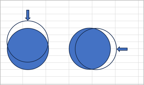
If you havent done this already, do this simple test. Chuck it in the collet & mark a reference line at the end of the collet. Put the DTI ball on the furthest outboard position of 'good shank' area. Ideally attach the mag base to the bed, not the carriage so that eliminates both carriage movement & bed wear. (Left) rotate the spindle & find the high deflection point (arrow), note the deflection say 0.0025", mark that ball tangent position on the shank, clock position like blue arrow & also the stickout position. (Right) ungrip reamer, rotate it in the collet say 90-deg, retorque to same amount & to same collet end stickout line. Rotate part & repeat with DTI on same stickout position. If the shank is identical diameter cross section but its neutral axis is bent you should be able to reproduce the same example 0.0025" deflection & coincident to same witness line. If you are getting something substantially different, something else is going on. You CAN dial things in with a bent reference dowel but you have to follow a specific procedure. But for diagnosing spindle issues it adds extra complexity.

viewing reamer shank from end. Dark blue = collet. Open circle = bent dowel effect
1794426365296.png
 
Got it, will do. A few clarifying questions:

1) You no longer want a deflection test, correct?

Yes, I am happy with your deflection results.

2) For my specific DTI, how would you want this exemplar reading recorded? With the red arrows indicating the two extremes of the dial sweep.
- 10.1 to 5.4?
- 13 ticks?
- Other?

Other. I just want the actual reading at that specific angle. In other words, where is the needle pointing on the DTI when the reamer is rotated to that angle.
 
Yes, I am happy with your deflection results.


Other. I just want the actual reading at that specific angle. In other words, where is the needle pointing on the DTI when the reamer is rotated to that angle.
So, to make sure I follow.

I am NOT adjusting the reamer in the collet (I had been doing that before).

I am simply rotating the spindle to 45° intervals and taking a static reading at each (I had been taking readings in motion before).
 
So, to make sure I follow.

I am NOT adjusting the reamer in the collet (I had been doing that before).

Yes, that is correct. Now I know why the readings made no sense though.

I am simply rotating the spindle to 45° intervals and taking a static reading at each (I had been taking readings in motion before).

Yes, we are trying to determine if the axis of rotation is concentric and if the bar is round.

The second is easier to do on a bench stand with the right metrology. But you don't have that stuff and we don't want to force you to get it.

I'll also go back and assess your previous results now that I think I know what you were doing.
 
@PeterT I will try to check that for you later.

@Susquatch Hmmm, not great results I fear. But as Peter noted this could be a poor reference tool (not that I have anything better currently).

AngleCollet 1Collet 2Extension 1Extension 2
0/3606.256.254.64.6
456.256.252.751.5
906.256.251.51.5
1356.256.253.03.0
1806.36.256.255.0
2256.86.88.07.0
2707.07.28.07.2
3157.07.27.88.0

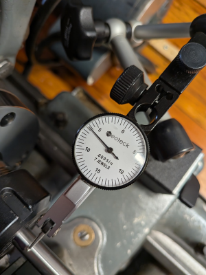
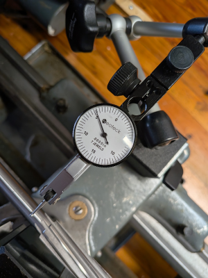
And for reference, here are the photos of Collet 1 at 0, and Extension 1 at 0, so you can see why I gave the reading the way I did.

Collet 1 at 0
1794438621183.png

Extension 1 at 0
1794438658836.png
 
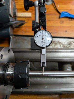
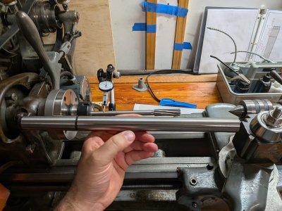
@PeterT at 1" out from the face of the collet your test came out clean - 0.5 deflection at all 4 points (meaning the collet and chuck are in the same place the entire time, and the reamer is rotated within the collet. I could move further out to where there's more flapping about on the indicator if that's of interest.
 

Attachments

  • PXL_20261111_235920220.jpg
    PXL_20261111_235920220.jpg
    1.4 MB · Views: 3
  • PXL_20261112_000323102.jpg
    PXL_20261112_000323102.jpg
    1.3 MB · Views: 3
But as Peter noted this could be a poor reference tool (not that I have anything better currently).

You have what you have.

But unfortunately, what you have is good for shit. It is not round and it is bent. We cannot learn anything from it except that we cannot learn anything from it.

This of course assumes you did what you say you did. I have no reason to think otherwise since your results repeated just fine.

We need to get you a good bar. Preferably 5/8 diameter like your pen arbours and 6" long or so.
 
And the alignment test bar literally just arrived. I'm skeptical of it (Amazon), but it's probably worth trying.
 

Attachments

  • PXL_20261112_015759600.jpg
    PXL_20261112_015759600.jpg
    1.9 MB · Views: 4
And the alignment test bar literally just arrived. I'm skeptical of it (Amazon), but it's probably worth trying.
I hope yours is better than mine. The morse taper on mine is very poor. I wish I could get it properly reground (or even afford to get it reground)....new one is probably cheaper and better🙄
 
I hope yours is better than mine. The morse taper on mine is very poor. I wish I could get it properly reground (or even afford to get it reground)....new one is probably cheaper and better🙄
Not holding my breath, but I figure it's worth a quick test tomorrow and a return if it's crap.
 
I hope yours is better than mine. The morse taper on mine is very poor. I wish I could get it properly reground (or even afford to get it reground)....new one is probably cheaper and better🙄

Quite a few members have these test bars. Some members like them.

I bought one myself to evaluate. After bench testing it, I felt like I wasted my money. Several other members felt the same way.

I suspect that many of those who liked it didn't have the ability to evaluate it properly themselves and simply believed or accepted the manufacturers specifications.

Even if they are as good as claimed, I don't personally think they are a good tool for lathe alignment. But a great many members do. So there is that.
 
I hope yours is better than mine.
Ditto. I have a Made in India special. Its ground very shiny & the diameter is within tenths all the way down. But... it went banana after a couple years, stress relieving itself I suspect. The theory of them is good if you happen to have a reliable one. An brand new offshore model can be had for under 50$. A Suburban or USA model is like 8X that. We have discussed this many times.

Not sure its quite applicable to what you are testing/validating but check out McGyver's website video on this subject (IIR when he was rebuilding his Shaublin).
 
Open to somewhat affordable recommendations!
An ordinary gauge pin will do just fine for your needs. We already discussed this in previous posts.

Lathe alignment itself is a different (but related) subject. There are lots of ways to do it. I can't vouch for all of them. I can only vouch for my own methods. In my opinion (an opinion not shared by all), an ordinary home shop made steel dumbell bar works just fine for lathe alignment purposes.
 
Back
Top