When does it start violating the rules, IF I were to....

DPittman

Ultra Member
Premium Member
. I did not realize that the Chinese had cheapened out on hobby lathes by dropping the feed bar. I see many that are only with a lead screw. Is this why you would want to do the ELS?
I think there are good reasons for an ELS regardless of whether a lathe has a feed bar or not and the lack or presence of it wouldn't affect my decision for or against a els. The Chinese were not the first to drop the feed bar/rod, there were north American made lathe many many years ago that did it. I had an Altlas lathe that used the leadscrew for any powered carriage travel. My present Asian made lathe also does not have a separate feed bar/rod but has a much improved design in that it is a keyed lead screw and the threads on the lead screw and half nuts are only used in threading. All other carriage and cross slide power feed is done through the key of the lead screw with no wear and tear on the threads of the lead screw and half nuts.
 

Matt-Aburg

Ultra Member
I think there are good reasons for an ELS regardless of whether a lathe has a feed bar or not and the lack or presence of it wouldn't affect my decision for or against a els. The Chinese were not the first to drop the feed bar/rod, there were north American made lathe many many years ago that did it. I had an Altlas lathe that used the leadscrew for any powered carriage travel. My present Asian made lathe also does not have a separate feed bar/rod but has a much improved design in that it is a keyed lead screw and the threads on the lead screw and half nuts are only used in threading. All other carriage and cross slide power feed is done through the key of the lead screw with no wear and tear on the threads of the lead screw and half nuts.
I see the historical lathes did not have a feed bar. This must have been an innovation when it came in, as it changed the need for change gears. Now, putting a slot through a feed-screw may improve functionality, but it is still a cheapened down machine.
 

DPittman

Ultra Member
Premium Member
I see the historical lathes did not have a feed bar. This must have been an innovation when it came in, as it changed the need for change gears. Now, putting a slot through a feed-screw may improve functionality, but it is still a cheapened down machine.
I'm not sure why you say it would change the need for change gears? Or are you referring to the ELS? I too initially thought of the keyed lead screw as cheapened down machine but now see it as a rather smart and efficient way to keep costs and complexities down when possible. The only slightly down side I can think of offhand is that there would be more wear on the bearings of the lead screw as it rotates anytime any sort of power feed is needed where as the feed bar system splits that wera and tear between two components. Can you think of other downsides?
 

Matt-Aburg

Ultra Member
I'm not sure why you say it would change the need for change gears? Or are you referring to the ELS? I too initially thought of the keyed lead screw as cheapened down machine but now see it as a rather smart and efficient way to keep costs and complexities down when possible. The only slightly down side I can think of offhand is that there would be more wear on the bearings of the lead screw as it rotates anytime any sort of power feed is needed where as the feed bar system splits that wera and tear between two components. Can you think of other downsides?
Removing part of the radial engagement on the thread and potential of a burr forming come to mind... Here is the video that made me aware that some don't have a feed-bar.

 
Last edited:

TorontoBuilder

Ultra Member
I was reading in about the ELS last night. I did not realize that the Chinese had cheapened out on hobby lathes by dropping the feed bar. I see many that are only with a lead screw. Is this why you would want to do the ELS? I want to introduce a different idea. This might be able to apply to the new style hobby lathes or any conventional lathe.

First of all, I will show the product that I have had for over 12 years. It is a 1440 lathe from CNC Masters in Sunny California. This is an Birmingham Lathe that was converted. (all his machines are imports starting with a (Birmingham). My particular machine was one of the first 1440 lathes he built. It has a 3 HP motor. The new models are 2 HP. Basically how it works is you turn off the feed bar and lead screw, engage a lever, and then use the CNC controlled ballscrews. If you were going to copy this idea I would really consider using a Masso controller instead.

See links below. I will post pictures of the ballscrews and how it is tied in.


That's basically the same model that my brother just picked up.

I'm going to show him this... If we get down your way early in the spring would you give us a tour of your shop and the rundown on your lathe?
 

jcdammeyer

John
Premium Member
Yes. My South Bend Heavy 10L with taper attachment is clearly a cheapened down machine with a single slotted lead screw and rack and pinion for the large hand wheel. Mine is even the cheaper model with a single lever gear box rather than dual. It was made in 1942 sold to the military in Edmonton and there is wear on the ways. I haven't engaged the gearbox in probably 8 years now.
My ELS can do metric threads.

"ELS! Nothing else works as well for your Lathe"


Matt-Aburg

Ultra Member
Yes. My South Bend Heavy 10L with taper attachment is clearly a cheapened down machine with a single slotted lead screw and rack and pinion for the large hand wheel. Mine is even the cheaper model with a single lever gear box rather than dual. It was made in 1942 sold to the military in Edmonton and there is wear on the ways. I haven't engaged the gearbox in probably 8 years now.
My ELS can do metric threads.

"ELS! Nothing else works as well for your Lathe"

I said that I noticed the OLD lathes only had the leadscrew. The feed bar was an innovation. Now they are reverting back with a modification by putting a slot through the leadscrew... I don't call old technology "cheapened down"... I call reverting back to save costs cheaping down.
 

TorontoBuilder

Ultra Member
John, do you sell complete kits, or is it more of a DIY open source type of thing?
I'd be interested in getting the price for a completed module where I don't have to do any soldiering or programming of a chip.

If the price is right I'd consider buying one just to test it out... I keep seeing cheap 12" lathes now, I could potentially put one in my basement just for turning engravers and such
 

jcdammeyer

John
Premium Member
I just changed the price list link in the web page to $150 for assembled and tested. No programming. It's turnkey other than you have to put in in a box and make a keypad overlay. I'm just working out what it costs me to do this. There are instructions on the groups.io site for making them. Or I'll walk you through it. Each one is tested by plugging into my Gingery Lathe and running through the operations.

One of the other group members created a 3D printed box with inset labels for it. This was a group project where other members contributed either parts or support or even software changes.

These have been in production since 2008. I had 200 boards assembled for the surface mount pick and place parts. I bought enough parts to make all 200 except I buy the processors and connectors as I need them. Even so I laid out $18,957 back in 2008. The first 25 kits went for component cost. After that I raised the price by $25 to cover the incidentals. I have about 80 left.

BTW, I only added the stuff below in my posting because it seems it's alright for Aburg Rapid Prototype to advertise with large block letters in his postings.

"ELS! Nothing else works as well for your Lathe"


Electronic Lead Screw Main Page
 

TorontoBuilder

Ultra Member
I just changed the price list link in the web page to $150 for assembled and tested. No programming. It's turnkey other than you have to put in in a box and make a keypad overlay. I'm just working out what it costs me to do this. There are instructions on the groups.io site for making them. Or I'll walk you through it. Each one is tested by plugging into my Gingery Lathe and running through the operations.

One of the other group members created a 3D printed box with inset labels for it. This was a group project where other members contributed either parts or support or even software changes.

These have been in production since 2008. I had 200 boards assembled for the surface mount pick and place parts. I bought enough parts to make all 200 except I buy the processors and connectors as I need them. Even so I laid out $18,957 back in 2008. The first 25 kits went for component cost. After that I raised the price by $25 to cover the incidentals. I have about 80 left.

BTW, I only added the stuff below in my posting because it seems it's alright for Aburg Rapid Prototype to advertise with large block letters in his postings.

"ELS! Nothing else works as well for your Lathe"


Electronic Lead Screw Main Page
well I can make a box and put on an overlay... $150 bucks is pretty painless to experiment. does that include free shipping :p
 

jcdammeyer

John
Premium Member
One other point that may not be clear about my ELS compared to the Arduino based units. Mine, like MACH3 uses a single pulse per rev on the spindle. At the time people were using surplus printer sensors. I have a Hall sensor and a small magnet on my South Bend and a disk with slot on my Gingery.

So my ELS cannot track a hand turned spindle. Minimum RPM is around 25. Max RPM for the tiny lathes is 6000 RPM which the Arduino units cannot do.

Also if you remove the DB25 from the back of the ELS (the one that goes to the Break Out Board, stepper drivers, 1PPR sensor and switches) and plug it into an older PC running MACH3 you have full CNC. For that one project where you need CNC. The designer of MACH2/3 also contributed to the ELS project.

I have started working on a 32 bit processor based ELS with full encoder support. The code conversion is really easy from 8 bit to 32 bit and runs more than 10x as fast. Other projects surfaced and moved this one back to #42. It would end up being a small module that plugs in place of the 40 pin DIP processor. AdaptorBoard-7.jpg

"ELS! Nothing else works as well for your Lathe"

Electronic Lead Screw Main Page
 

jcdammeyer

John
Premium Member
well I can make a box and put on an overlay... $150 bucks is pretty painless to experiment. does that include free shipping :p
Shipping in Canada used to be about $18. Now it's over $25 including their fuel surcharges. Kind of shocking considering again, from China a similar sized package worth $100 ships for free. Yet another way to drive out domestic production.
 

TorontoBuilder

Ultra Member
Shipping in Canada used to be about $18. Now it's over $25 including their fuel surcharges. Kind of shocking considering again, from China a similar sized package worth $100 ships for free. Yet another way to drive out domestic production.
I tend to try to stick with a small flat rate box whenever I need to ship but yeah it's about 23 bucks....

The last letter I sent never got to its destination via Canada Post. I used a "permanent" stamp. It had cash inside... but no politics so I can't say more
 

Dabbler

ersatz engineer
John I just read your manual and I am very impressed. I love the fact you've put in both metric and imperial threading - something Rocketronics seems to be reluctant to do. I'm not in a 'gotta haveit rightaway' mode but I think I'd love to get the 32 bit full encoder version when it becomes available. I may try one of your current versions "when I have the time".

Very impressive!
 

Matt-Aburg

Ultra Member
That's basically the same model that my brother just picked up.

I'm going to show him this... If we get down your way early in the spring would you give us a tour of your shop and the rundown on your lathe?
Here are the photos of how the lather is both conventional and CNC. See the lever shifts back and forth for the different modes. The "X" axis motor is behind the cross-slide. I am in the middle of restoring this machine and so forgive me for the dirt and surface rust. The machine has sat for a number of years while I worked on Molds.
@TorontoBuilder
 

Attachments

  • DSCN1405.JPG
    DSCN1405.JPG
    550.3 KB · Views: 11
  • DSCN1406.JPG
    DSCN1406.JPG
    403.8 KB · Views: 12
  • DSCN1407.JPG
    DSCN1407.JPG
    387 KB · Views: 11
  • DSCN1412.JPG
    DSCN1412.JPG
    382.8 KB · Views: 11
  • DSCN1413.JPG
    DSCN1413.JPG
    411.1 KB · Views: 10
  • DSCN1411.JPG
    DSCN1411.JPG
    552.7 KB · Views: 11

jcdammeyer

John
Premium Member
John I just read your manual and I am very impressed. I love the fact you've put in both metric and imperial threading - something Rocketronics seems to be reluctant to do. I'm not in a 'gotta haveit rightaway' mode but I think I'd love to get the 32 bit full encoder version when it becomes available. I may try one of your current versions "when I have the time".

Very impressive!
Thank you. It is the culmination of the work and help and contributions of a number of people over more than a year. Using it is like using your lathe manually for the most part.

I'm currently working on tracking the spindle center line more than just for SFM rather than RPM and adding a tool table. The RS232 port on all of them, although not used in the past, now serves as the method of updating firmware and will ultimately also allow controlling a VFD for spindle speed to be able to face at a constant SFM. Project #42...

Originally I wanted to use a TI Digital Signal Processor and even went as far as to make a companion board for an F2812 processor demo board. But the compiler and IDE for programming were expensive and the group talked me into using the free PIC compiler and MPLAB. My first prototypes also has a surface mount processor and at that point I had enough boards for my own use.

But I redid it for the DIP processor and spent gobs of money. I've used it for a coil winder to track number of turns. I've run it as a power feed controller for the knee on my mill. Handy to move it out of the way and then return automatically to the same spot. And of course as a division master for my smaller rotary table. All the symmetrical parts for the CNC router were done with that.
1670965903621.png
 

Attachments

  • Electronic-Gear-Control.pdf
    557.3 KB · Views: 4

Janger

(John)
Administrator
Vendor
@jcdammeyer Hey John - looking at your ELS kit - are there other things that need to be added? MPG dial, power supply, project box, stepper motor? and ?
 

jcdammeyer

John
Premium Member
@jcdammeyer Hey John - looking at your ELS kit - are there other things that need to be added? MPG dial, power supply, project box, stepper motor? and ?
Yes. It was a kit designed to save the end user money by sourcing many parts locally in their country. I sold very few in Canada. Others went to Australia, UK, Europe, South Africa etc. To ship motors to Canada and then reship to another country was by consensus way too expensive.

So users bought the following themselves.
1. 12V AC adaptor for the ELS
2. Appropriate power supply for their motor systems
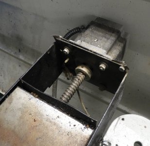
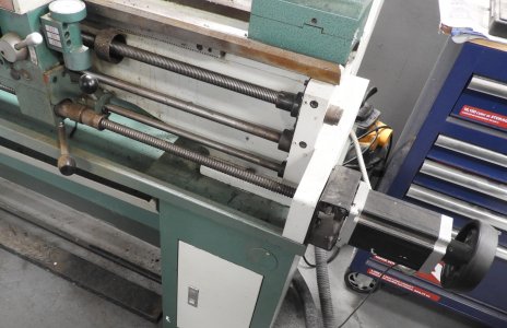
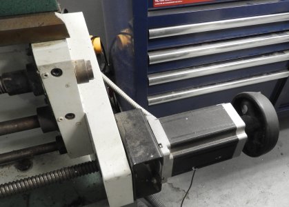
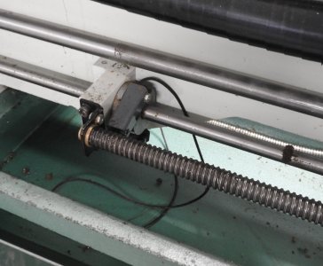
3. Appropriate motor, couplers or belts and pulleys etc for their unique system.
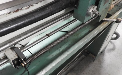
4. Either optical or hall sensor for the 1 PPR spindle.
5. A box of some sort for the ELS and for their motor hardware.
6. I was selling keypad overlays. A friend on Saltspring made a silk screen for the white mask. I can now provide that here since I have the laminater and laser printer.
7. Also recommended was some sort of break out board to simplify swapping back and forth between a PC for MACH3 or LinuxCNC and the ELS. This way you can have an quadrature encoder connected to the lathe but use a 1 PPR index pulse for the ELS and MACH3 but full quadrature for LinuxCNC if wanted.
Note that to combat electrical noise the ELS requires a long index pulse rather than that short one from full quadrature encoders. There are ways to make that work though.

I now supply a 3D printed knob for the MPG. It's a detented 16 pulse per rev (64 units per rev in quadrature) with a momentary button when you press down on it. You can select 00.001 or 0.010 etc for distance per click. I bought enough of those to make all 200 boards. A few years ago that model of encoder was discontinued so a new PC board would be required anyway.

Or, since there's a spot on the board for a keypad connector one could built the board without the buttons and make a separate board that has more than 35 buttons and a panel mounted MPG. The LCD pinout is also designed for up to a 4 line unit but that does require other software.

I built just this one to demo the concept. Haven't looked further into LCD displays with 4 lines. Between the ENTER and the L-JOG button is the keyboard expansion strip. Wires or header pins could be soldered where the MPG goes for an external encoder from China.

It's no longer worth the money to put the stepper motor driver right on the PC board.
4X24Display.jpg

One project I did with it added this relay and optically isolated input board. Also had A/D and stationary battery current sensor. It plugged into the jumper block on the bottom of the ELS.
GCC-Interface-2.0.jpg
And was designed to also run stand alone with it's own processor and RS232 + CAN bus connection.

ICC_Interface.jpg
 

jcdammeyer

John
Premium Member
Oh one other thing. Unless you dive into the software it's not really mentioned anywhere that the menu system on the ELS is tree structured with 4 branches representing the 4 'soft keys' below the display. So each of the branches can either point to another branch with 1 to 4 more branches with appropriate text above each 'soft key' or be a final value with type number or flag.

So adding features isn't horrendously complicated. Add more branches to the tree and you suddenly have more menu entries. In that menu is a link to the new code to do something with it. That's why it was so easy to design that Generator Charge Controller with fewer buttons and totally different menus etc.

Remotely start and stop an ONAN generator. Switch on remotely the contacter to connect the battery bank to the system.
GCC-Box.jpg
This project didn't even need the 'soft key' buttons under the display.
 
Last edited:
Top